
Wind turbine nacelle with cooler top

a technology of wind turbines and nacelles, applied in the direction of propellers, propulsive elements, water-acting propulsive elements, etc., can solve the problems of slow wind down, and achieve the effect of cooling the generator and other equipment inside the nacelle more efficiently

Inactive Publication Date: 2015-05-26
VESTAS WIND SYST AS
View PDF17 Cites 3 Cited by
  • Summary
  • Abstract
  • Description
  • Claims
  • Application Information

AI Technical Summary

Benefits of technology

The present invention relates to an improved wind turbine nacelle that can cool the generator and other equipment inside the nacelle more efficiently than prior art solutions. This is achieved by incorporating a longitudinally extending face on the nacelle that can improve cooling performance.

Problems solved by technology

When wind flows along a surface, the friction on the surface will slow the wind down.

Method used


Image

  • Wind turbine nacelle with cooler top
  • Wind turbine nacelle with cooler top
  • Wind turbine nacelle with cooler top

Examples


Embodiment Construction

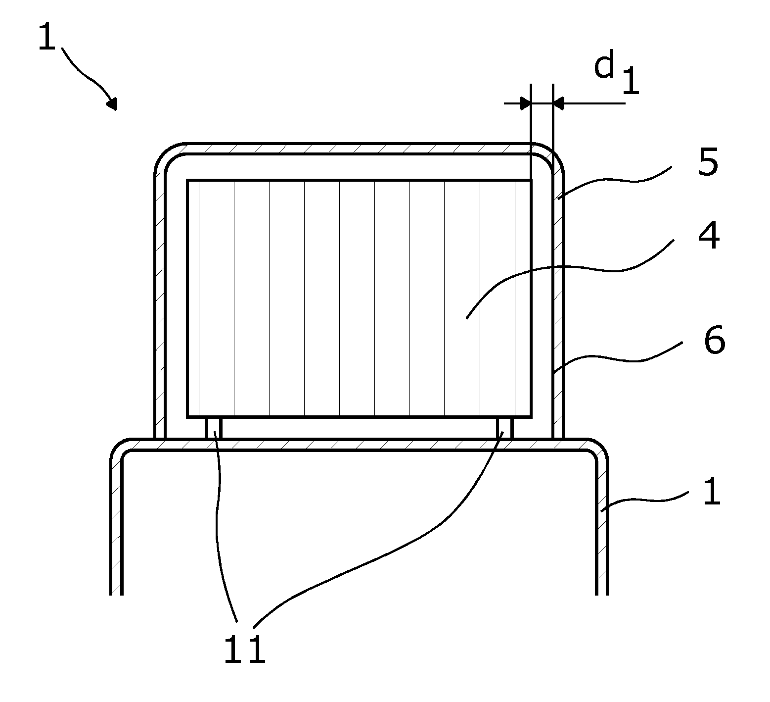
[0069]A wind turbine nacelle 1 is situated on a tower and has a front facing a hub in which a plurality of rotor blades 8, normally three blades, is fastened. The wind turbine nacelle 1 houses a generator and other equipment used for driving the conversion process of wind energy to electricity—also called the drive train. When producing electricity, the drive train produces a lot of heat, resulting in a less effective conversion process.

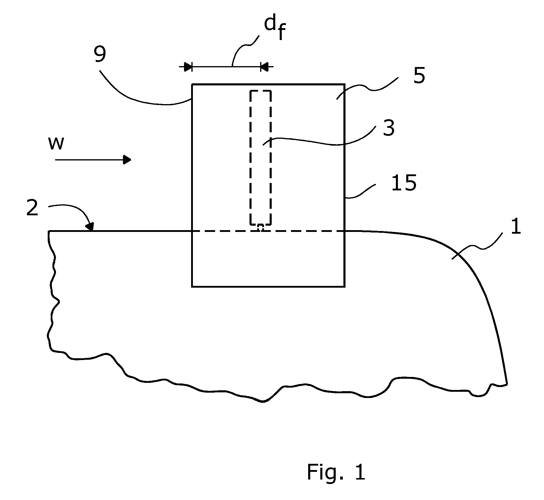
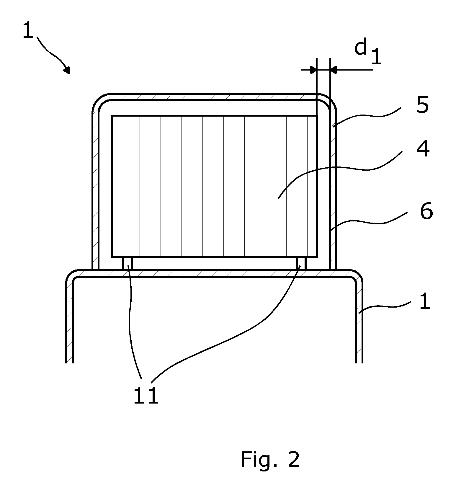
[0070]In order to cool the equipment and other parts of the nacelle, a cooling device 3 is arranged outside the nacelle 1. Wind flowing along a longitudinal extension of the nacelle flows in through at least one cooling area 4 of the cooling device 3 and cools a fluid within the cooling device. The cooled fluid exchanges heat with the parts of the nacelle 1 or equipment to be cooled.

[0071]The present invention will mainly be described in connection with an upwind wind turbine, i.e. a wind turbine where the nacelle is placed downwind from the wind tur...


PUM


Abstract

The present invention relates to a wind turbine nacelle having a first face with a longitudinal extension in a wind direction, comprising a cooling device having a cooling area and extending from the first face of the nacelle, and a cover having at least one inner face, the cooling device being enclosed by the first face of the nacelle and the inner face of the cover. A first distance between at least one of the faces and the cooling area is at least 30 mm.

Description

FIELD OF THE INVENTION[0001]The present invention relates to a wind turbine nacelle having a first face with a longitudinal extension in a wind direction, comprising a cooling device having a cooling area and extending from the first face of the nacelle, and a cover having at least one inner face, the cooling device being enclosed by the first face of the nacelle and the inner face of the cover.BACKGROUND ART[0002]A wind turbine converts wind power into electrical energy by using a generator placed among other equipment in the nacelle of the wind turbine. When the generator converts energy, the walls and the air surrounding the equipment are heated and the equipment itself is thus heated, too.[0003]When the equipment is heated, the efficiency with which the conversion occurs is substantially decreased. In order to cool the equipment, the walls and the air surrounding the equipment are cooled down by means of a heat sink positioned on top of the nacelle as shown in WO 2008 / 131766 A2....

Claims


Application Information

Patent Timeline
Patent Type & Authority Patents(United States)
IPC IPC(8): F03D11/00
CPCF03D11/00F05B2260/20F05B2260/64Y02E10/722Y02E10/726F03D13/40F03D80/30F03D80/60Y02E10/72
Inventor SIVALINGAM, KRISHNAMOORTHIBAHUGUNI, ANANDKANDASAMY, RAVINARASIMALU, SRIKANTHGREVSEN, JOHN K.NYVAD, JESPERTIETZE, PAUL T.
Owner VESTAS WIND SYST AS
Learn More