Method for treating spent abrasive slurry

a technology for abrasives and slurry, which is applied in the direction of multi-stage water/sewage treatment, other chemical processes, separation processes, etc., can solve the problems of ineffective slurry, large cost, and small system which can be located and operated near the point of use to regenerate the spent slurry from a local user, etc., to achieve sufficient efficiency and reduce the viscosity , the effect of reducing the viscosity

Active Publication Date: 2015-01-27
PALL CORP
View PDF21 Cites 2 Cited by
  • Summary
  • Abstract
  • Description
  • Claims
  • Application Information

AI Technical Summary

Benefits of technology

[0019]The first sedimentation steps may be accomplished by simple gravity sedimentation. Advantageously, the preferred embodiments of the present invention make use of a centrifugal field in this step which allows for more compact equipment.
[0021]Its use for preparing a fresh slurry greatly reduces fines contaminations and increases slurry life time even if combined with a solids concentrate obtained in a conventional way by the centrifugation of spent slurries, which is due to the excellent quality of this liquid.
[0022]In a preferred embodiment the filtrate is split and one portion thereof is mixed with the spent slurry in the feed of the first sedimentation step. This lubricant recycling dilutes the spent slurry increasing the distance between the particles and, as a consequence, lowers the particle-particle interactions and improves classification efficiency of the first sedimentation step. Thereby, the amount of fines polluting the coarse abrasive particles obtained in the sludge of the first sedimentation step is diminished. The combination of the regenerated lubricant fluid and the solids concentrate obtained according to this embodiment provides fresh slurry of excellent quality and further increased slurry life time.
[0025]This allows low-cost equipment, and the efficiency provided by a static mixer is sufficient for the purpose.
[0026]In an even more preferred embodiment, the one portion of the regenerated lubricant fluid used to dilute the spent slurry is heated to an elevated temperature prior to admixing the same with the spent slurry. The resulting mixture of spent slurry and regenerated lubricant fluid is at an elevated temperature, preferably at about 35° C. or more, more preferably at a temperature of 50° C. or more. The elevated temperature lowers the viscosity of the slurry / lubricant mixture. The lower viscosity accelerates the sedimentation of the particles within the fluid and such overcompensates the increased feed rate into the centrifuge and to the cross-flow separation device. It furthermore improves the classification efficiency and thus provides a higher quality first solids concentrate.
[0027]Heating the regenerated lubricant fluid prior to admixing the same with the slurry is of advantage over a direct heating of the spent slurry itself. Heating the regenerated lubricant fluid obtained in the present invention prior to admixing the same with spent slurry avoids the risk of scaling, encrustation, fouling and abrasion of heat transfer surfaces, since the liquid passing the heater practically no particles and almost no colloidal components.

Problems solved by technology

The metal of the cutting wires (primarily iron) is another source for particulate contaminations due to surface wear of the wire.
When the slurry finally becomes ineffective, i.e., spent or exhausted, it must be discarded.
There are numerous disadvantages to this method, and the most prominent one is its complexity.
The large number of operations needed and in addition the high degree of interactions between these operations would make a small system which can be located and operated near the point of use to regenerate the spent slurry from a local user rather expensive.
The transport costs involved in the regeneration of the abrasive slurry are therefore substantial.
However, the heating of rather highly concentrated slurry creates the risk of scaling, encrustation, fowling and abrasion of heat transfer surfaces resulting in lower heat transfer efficiency, limited life time of the heater and increased energy costs.
Although this principle necessitates less operations than the first one described above and although it might be easier installed as a point-of-use process, two major disadvantages prevent the method from being widely used.
First of all, the second centrifuge is not capable of clarifying the overflow fraction of the first centrifuge satisfactorily to provide a readily re-usable lubricant.
Secondly, the classification effect in the first centrifuge is far from being ideal: Substantial amounts of fines leave the centrifuge with the unspent abrasive particles contaminating fresh slurries prepared with the recovered abrasives in addition and limit the life time of the fresh slurries.
The reasons for this are some limitations of the centrifugal process:i) High solids concentration of a common saw sludge favor particle-particle interactions; large particles can entrain fines along with them, forcing them to leave the centrifuge the wrong way out.

Method used


Image

  • Method for treating spent abrasive slurry
  • Method for treating spent abrasive slurry
  • Method for treating spent abrasive slurry

Examples


Embodiment Construction

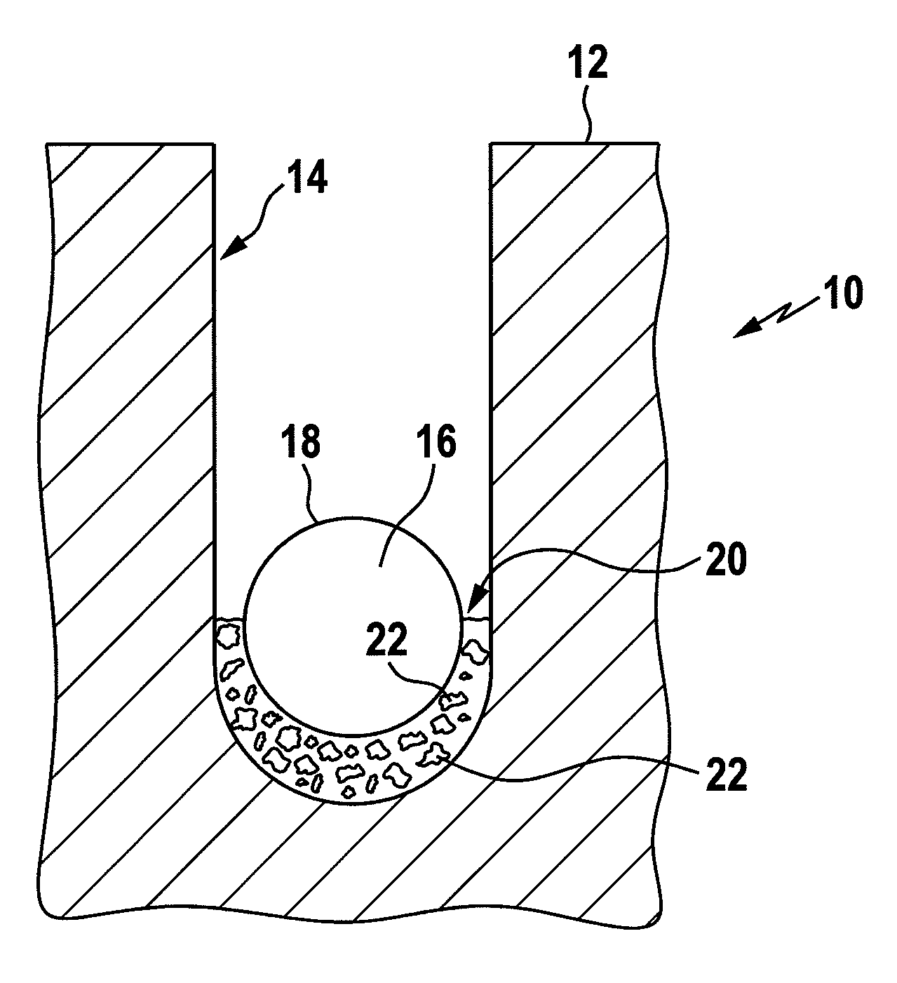
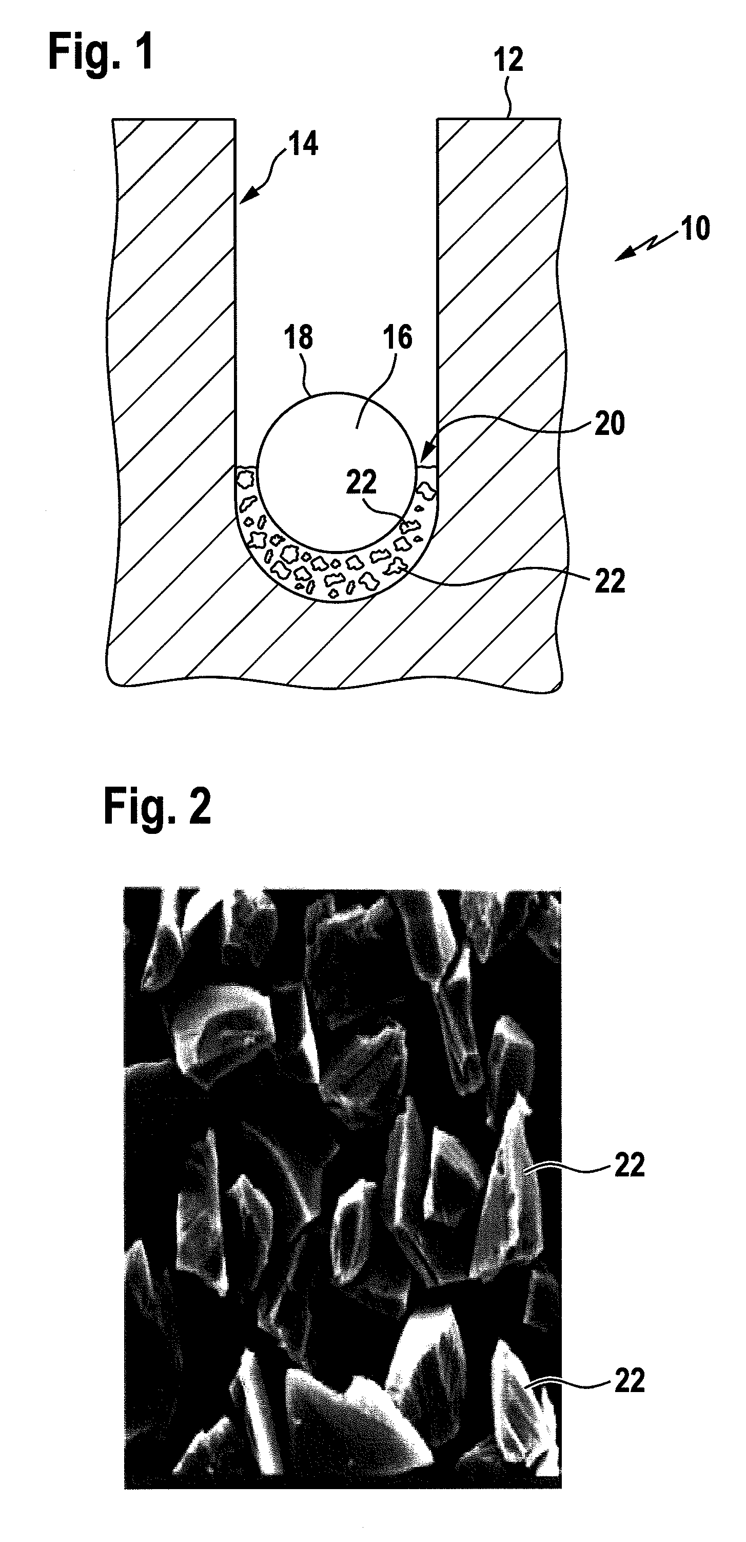
[0038]FIG. 1 shows a cut-out of a cross-sectional representation of an ingot body 10 of, e.g., silicon which has been cut already to a certain depth starting from an outer circumference 12 to produce a kerf 14. Within kerf 14, a cutting wire 16 is positioned which has an approximately circular cross-section and a smooth outer surface 18. In the portion of kerf 14 where the cutting wire 16 contacts the ingot body 10, an abrasive slurry 20 is present to cool and lubricate the cutting tool and the substrate material of the ingot while at the same time supporting abrasion of the substrate material of ingot 10. To that effect, the abrasive slurry 20 includes besides a viscous lubricant fluid abrasive particles or grains 22 which are shown in FIG. 2 in more detail. The average size of the abrasive grains 22 shown in FIG. 2 is about 20 μm and these abrasive grains 22 work on the substrate material of ingot 10 driven in a longitudinal motion of cutting wire 16, a motion which would be perpe...


PUM

PropertyMeasurementUnit
temperatureaaaaaaaaaa
sizesaaaaaaaaaa

Abstract

A method for treating spent abrasive slurry obtained from cutting a body of a substrate material into wafer-like slices, the slurry comprising a lubricant fluid, unspent abrasive particles and fines, is disclosed, method comprising separating the spent slurry in a first sedimentation step into a solids concentrate comprising unspent abrasive particles and a solids depleted slurry; and subsequently separating the solids depleted slurry by cross-flow filtration into a fines containing fraction and a solids and fines depleted regenerated lubricant fluid.

Description

BACKGROUND OF THE INVENTION[0001]The present invention relates to a method for treating spent abrasive slurry obtained from a process for cutting a body of a substrate material into wafer-like slices. Typically, abrasive slurries are applied in the cutting of semiconductor materials, e.g., ingots from single crystals or polycrystalline silicon, GAs and Ge by means of wire saws into semiconductor wafers and comprise a lubricant or cooling fluid of high viscosity such as a mineral oil or water-soluble liquids (e.g., polyethylene glycol) and a particulate matter from abrasives such as silicon carbide.[0002]While the wires used for cutting the ingots into slices have a smooth surface, the cutting effect is obtained by use of the highly viscose abrasive slurry which is fed to the contact area of the cutting wire and the substrate material to be cut into slices.[0003]During the cutting operation, the substrate material is ground at a so-called saw kerf into powdery material. The slurries ...

Claims


Application Information

Patent Timeline
Patent Type & Authority Patents(United States)
IPC IPC(8): B01D37/00B01D21/00B01D36/04C09K3/14B24B57/00C10M175/00
CPCC10M175/0058B24B57/00C10M2201/061C10M2209/104C10N2270/00C10N2070/00
Inventor BERNDT, ROLFRUTH, JOCHEN
Owner PALL CORP
Why Eureka
Try Eureka