Substrate transfer equipment and high speed substrate processing system using the same

a technology of substrate processing and transfer equipment, which is applied in the direction of electrical equipment, thin material processing, article separation, etc., can solve the problems of increased apparatus cost and installation cost, increased vacuum system required for maintaining the transfer chamber in a vacuum state, and loss of time, so as to achieve easy implementation, increase the processing rate of the system, and increase the overall productivity of the substrate

Inactive Publication Date: 2015-06-09
NEW POWER PLASMA CO LTD
View PDF12 Cites 7 Cited by
  • Summary
  • Abstract
  • Description
  • Claims
  • Application Information

AI Technical Summary

Benefits of technology

[0070]According to the present invention, substrates before and after being processed are rapidly exchanged in the substrate processing system in which a plurality of substrates is simultaneously or continuously processed, so that processing rate of the system can be increased and overall productivity of the substrates can be increased. Since a substrate transfer apparatus to simultaneously load and unload the substrate is provided, the process chamber is very easily implemented to process the plurality of substrates. Time for transferring substrates is reduced and as a result productivity increases. The area and width of the system are significantly reduced so that apparatus cost and installation cost can be minimized. Respective chambers for processing, aligning, and cooling the substrates are overlapped with each other so that a total bottom area of the substrate processing system can be reduced. Due to this, the clean room can be narrower than the conventional one and costs for the air-conditioning apparatus of the clean room can also be reduced. Moreover, since the traveling distance of the atmospheric pressure transfer robot for transferring the aligned substrates to a place for the process of the substrates or for transferring the processed substrates to the place for the cooling of the substrates is short and unnecessary operation such as a direction change does not need, time for the transfer of the substrates can be reduced and yield thereof can be increased.

Problems solved by technology

However, although the plurality of substrates is simultaneously (or continuously) processed in the process chamber, when substrates before and after being processed are not effectively exchanged in the process chamber, loss of time is generated.
Moreover, when a conventional cluster system includes a hexagonal transfer chamber (basically, including four process chambers and two load lock chambers), due to the area occupied by the transfer chamber, the area of the cluster system and the width of the entire cluster system that is important to the arrangement of the cluster system in a manufacturing line increases more than a desired width and the scale of a vacuum system required for maintaining the transfer chamber in a vacuum state increases, so that apparatus cost and installation cost increase.

Method used


Image

  • Substrate transfer equipment and high speed substrate processing system using the same
  • Substrate transfer equipment and high speed substrate processing system using the same
  • Substrate transfer equipment and high speed substrate processing system using the same

Examples


embodiment 1

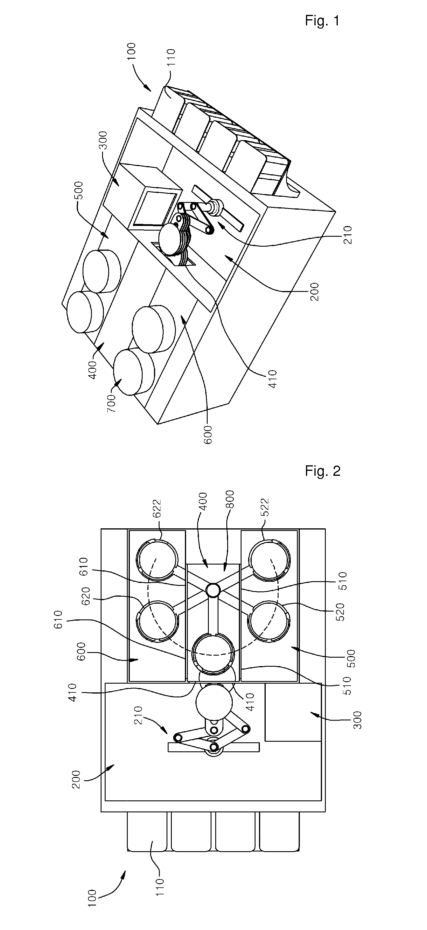
[0112]FIG. 1 is a view illustrating an overall structure of a substrate processing system according to a first embodiment of the present invention, and FIG. 2 is a plan view illustrating the substrate processing system of FIG. 1. Referring to FIG. 1, the substrate processing system according to the embodiment of the present invention includes first and second process chambers 500 and 600 and a transfer chamber 400 disposed between the first and second process chambers 500 and 600. An index 100 in which a plurality of carriers 110 are mounted is installed in front of a load lock chamber 200. The index 100 is referred to as an equipment front end module (hereinafter, referred to as ‘EFEM’) and is referred to as including the load lock chamber on occasion. If necessary, the load lock chamber 200 may include a cooling chamber 300 for cooling the processed substrates.

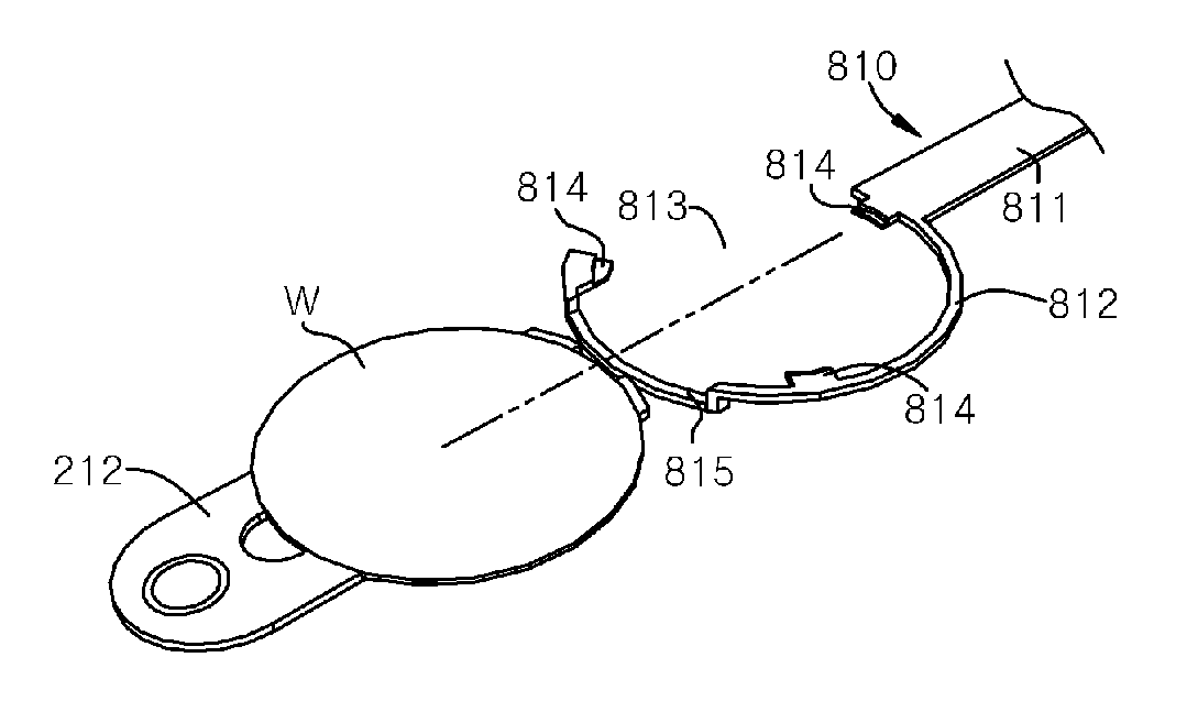
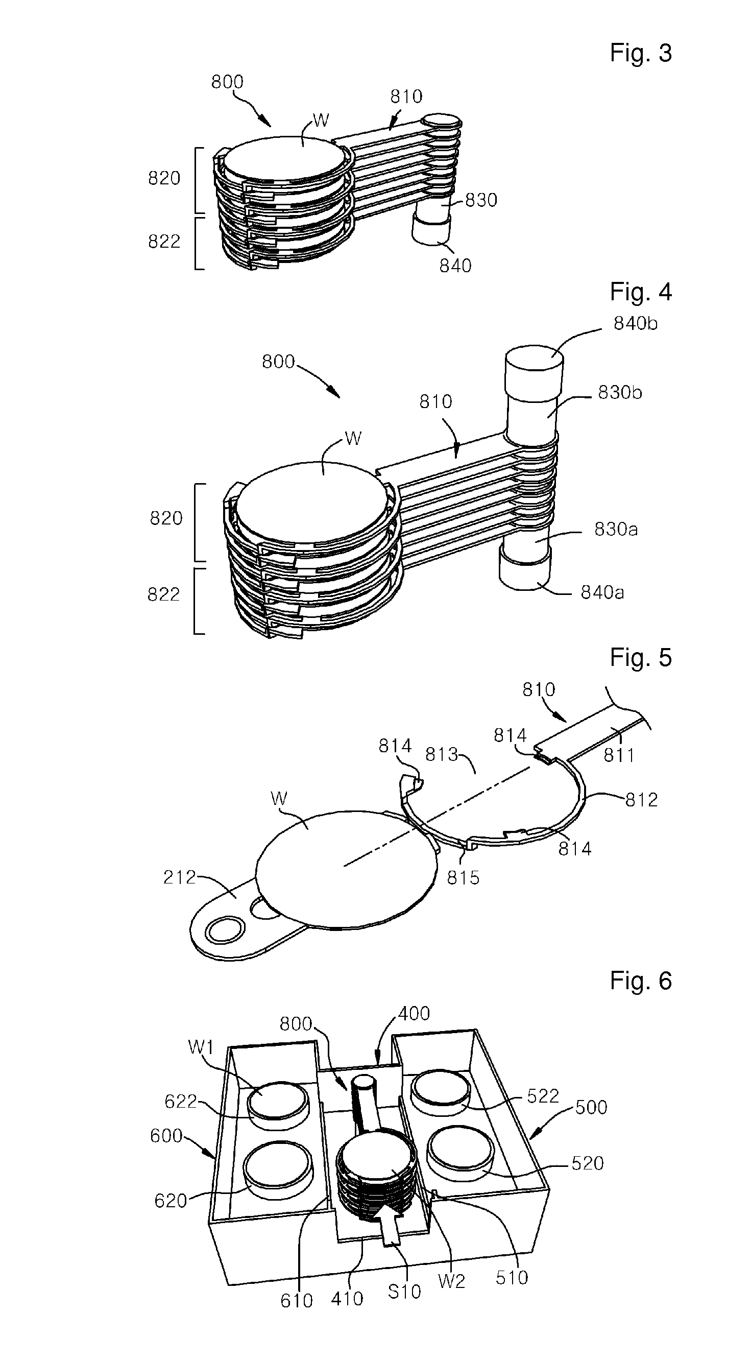
[0113]The load lock chamber 200 includes an atmospheric pressure transfer robot 210 operated under the atmospheric pressur...

embodiment 2

[0137]FIG. 17 is a plan view of a substrate processing system according to a second embodiment of the present invention and FIG. 18 is a view illustrating the flow of substrates transferred by the substrate transfer apparatus.

[0138]Referring to drawings, the substrate processing apparatus according to the second embodiment of the present invention includes the same structure as the first embodiment, and further includes a load lock chamber 250 having an atmospheric pressure transfer robot 260 disposed and an index 150 in the rear side. A fourth substrate entrance 420 is further formed between the transfer chamber 400 and the rear load lock chamber 250. In the substrate processing system, the substrates before being processed are loaded to the front side and the processed substrates are unloaded to the rear side. Here, the rear load lock chamber 250 may include a cooling chamber 300 to cool the substrates. Arrows S100 to S130 in FIG. 18 indicate the flow of the substrates before bein...

embodiment 3

[0142]FIG. 21 is a view illustrating an overall structure of a substrate processing system according to a third embodiment of the present invention and FIG. 22 is a plan view of the substrate processing system of FIG. 21.

[0143]Referring to FIGS. 14 and 15, the substrate transfer apparatus according to this embodiment of the present invention includes first and second process chambers 1500 and 1600 and a transfer chamber 1400 disposed therebetween. An index 1100 in which a plurality of carriers 1110 are mounted is installed in front of a load lock chamber 1200. The index 1100 is referred to as an equipment front end module (hereinafter, referred to as ‘EFEM’) and is referred to as including the load lock chamber on occasion. If necessary, the load lock chamber 1200 may include a cooling chamber 1300 for cooling the processed substrates.

[0144]The load lock chamber 1200 includes an atmospheric pressure transfer robot 1210 operated under the atmospheric pressure. The atmospheric pressur...


PUM


Abstract

There are provided a substrate transferring apparatus for continuously loading / unloading a plurality of substrates in and from a process chamber to reduce time spent on transferring the substrates and to improve productivity and a substrate processing system using the same. The substrate transfer apparatus is installed in the transfer chamber and transfers substrates between first and second process chambers which is positioned lateral sides of the transfer chamber and a load rock chamber. The substrate transfer apparatus includes a driving unit to supply a rotational force, a spindle connected to the driving unit, first swivel plate arms to load / unload substrate to / from first process chamber, and second swivel plate arms to load / unload substrate to / from second process chamber. Since substrates before and after being processed are rapidly exchanged during the simultaneous or continuous process of plural substrates, processing rate increases and overall productivity can be increased.

Description

TECHNICAL FIELD[0001]The present invention relates to a substrate transferring apparatus and a substrate processing system, and more particularly, to a substrate transferring apparatus for continuously loading / unloading a plurality of substrates in and from a process chamber to reduce time spent on transferring the substrates and to improve productivity and a substrate processing system using the same.BACKGROUND ART[0002]Recently, a cluster system capable of simultaneously process a plurality of substrates is commonly employed in substrate processing systems for manufacturing liquid crystal displays, plasma panel displays, and semiconductor devices.[0003]In general, the cluster system refers to a multi-chamber type substrate processing system including a transfer robot (or a handler) and a plurality of substrate processing modules provided around the transfer robot.[0004]The cluster system includes a transfer chamber and the transfer robot provided in the transfer chamber to be free...

Claims


Application Information

Patent Timeline
Patent Type & Authority Patents(United States)
IPC IPC(8): H01L21/677H01L21/687H01L21/67
CPCH01L21/67742H01L21/68707H01L21/67196H01L21/67745Y10S414/139Y10S414/141Y10S901/30
Inventor WI, SOON-IM
Owner NEW POWER PLASMA CO LTD
Why Eureka
Try Eureka