Air support apparatus

a technology of air support and air mattress, which is applied in the field of adjustable air mattress for beds, can solve the problems of increasing the remaining volume of the enclosure, increasing the pressure of the sleeping process, and reducing the comfort of sleeping, so as to reduce heat generation, enhance the deflection of the rigid plate, and reduce the effect of heat generation

Inactive Publication Date: 2015-06-16
LEVENTHAL ROBERT D +1
View PDF4 Cites 7 Cited by
  • Summary
  • Abstract
  • Description
  • Claims
  • Application Information

AI Technical Summary

Benefits of technology

[0075]It is an additional object of the present invention to provide a sonic device that has a sonic transducer design that creates acoustic waves generated by a rigid transmission plate through movement by the translation of significant solid mass. This construction will provide high magnitudes of acoustic energy to the directly coupled air massaging device or directly coupled to the user's air cavity. It also ignores the normal standard in sound generation to provide large and significant air modulations by cone or panel displacement wherein the coil is the moving member.
[0076]It is a further object of the present invention to provide a sonic device which is improved by centrally locating the improved sonic transducer within a central opening on a flat rigid transmission plate. This construction enhances deflection of the rigid plate by eliminating the central portion and providing easer movement of the rigid plate.
[0077]It is still an object of the present invention to provide a sonic device which can be further enhanced by winding the coil twice in separate directions in order to create both significant flux and reduced heat generation due to reduction of resistance.
[0078]It is still another object of the present invention to provide a sonic device with a foam m

Problems solved by technology

The prior art air mattress construction have problems which can cause discomfort and disruption to the sleeping process.
When depressed, the enclosure depresses slightly in the vicinity of the loading and also increases pressure in the remaining volume of the enclosure.
The response is both resistive and bouncy, which are undesirable characteristics as far as the comfort of the user is concerned.
None of these prior art patents teach an air spring bedding system, resting or therapeutic structur

Method used


Image

  • Air support apparatus
  • Air support apparatus
  • Air support apparatus

Examples


Embodiment Construction

[0148]Although specific embodiments of the present invention will now be described with reference to the drawings, it should be understood that such embodiments are by way of example only and merely illustrative of but a small number of the many possible specific embodiments which can represent applications of the principles of the present invention. Various changes and modifications obvious to one skilled in the art to which the present invention pertains are deemed to be within the spirit, scope and contemplation of the present invention as further defined in the appended claims.

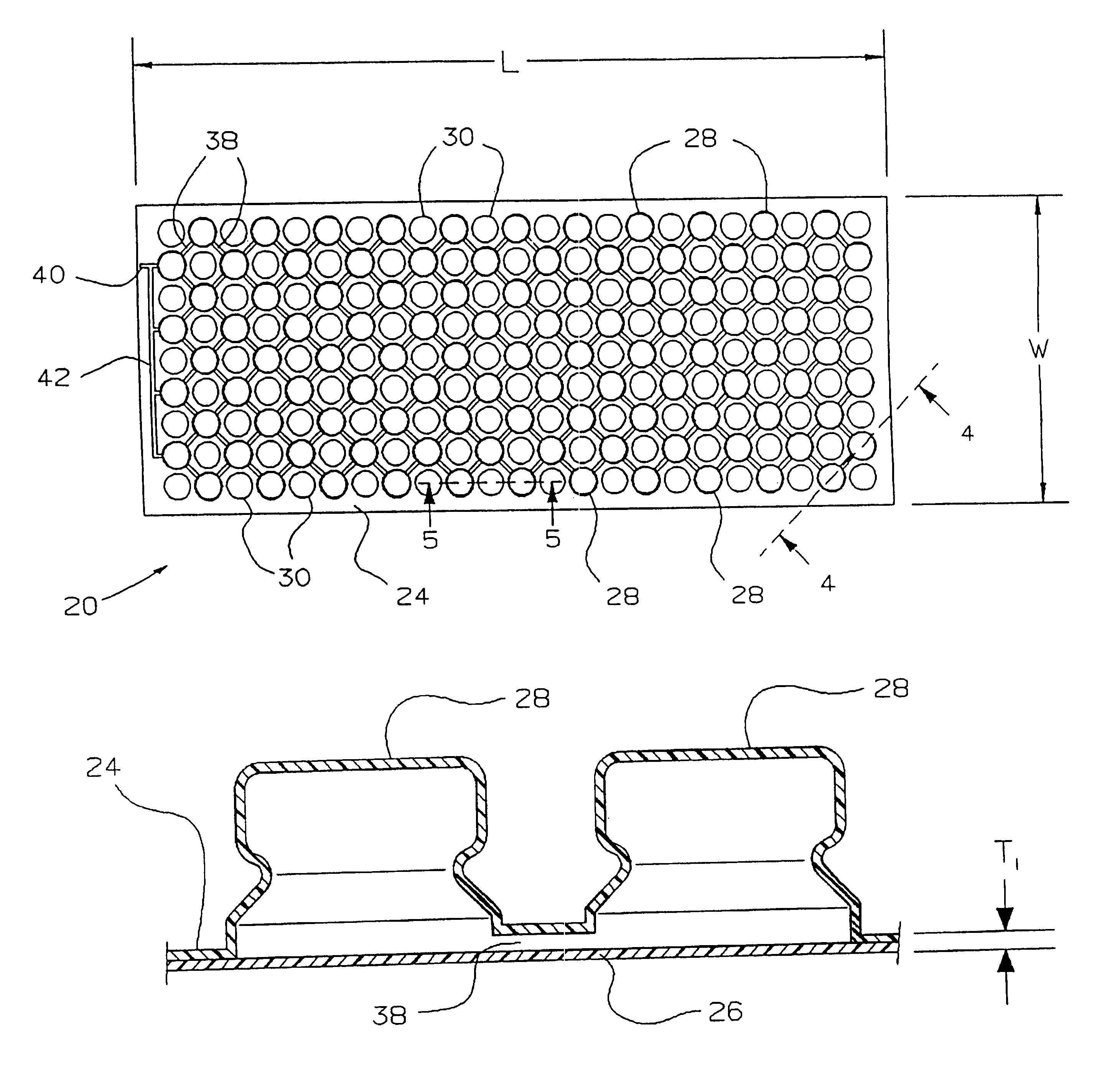
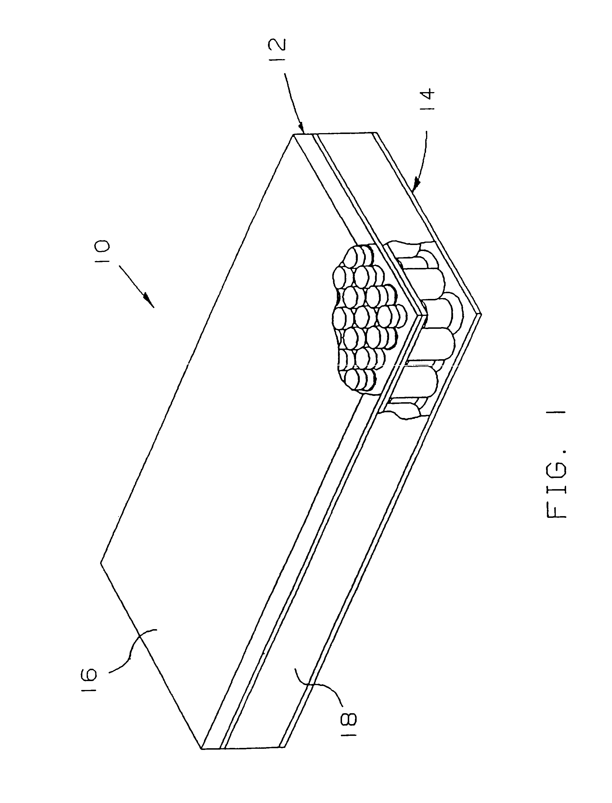
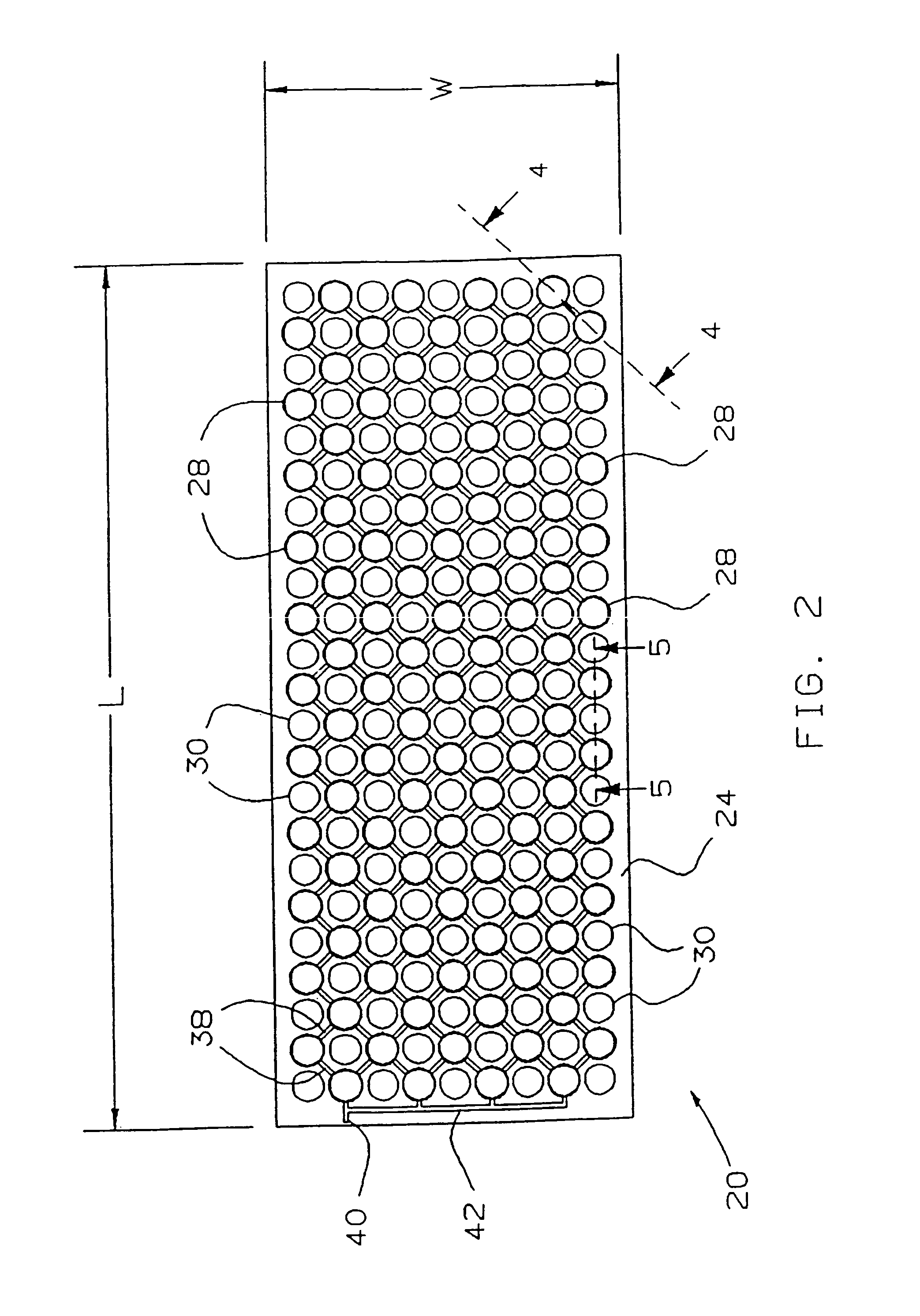
[0149]Described briefly, the present invention is an air spring bedding system. The concept of the present invention is the construction of a bedding, resting or therapeutic structure by two different air support structures to create a matrix surface that is both supportive and pliable with minimal surface tension.

[0150]Referring to FIG. 1, there is shown at 10 a preferred embodiment of the present inventi...


PUM


Abstract

A two layer air support apparatus having at least two preformed air node circuits, where a top layer is radio frequency welded to a bottom layer for providing cyclic support to periodically shift pressure between different parts of a user's anatomy. The periodic shifting of the area supported by a user's anatomy over a period of time improves comfort and blood circulation. It is well known that periodic redistribution of skin pressure can help prevent some of the negative effects experienced through extended usage of beds and chairs. Additionally, enhancement of health and cosmetic improvement to vigorous individuals is suggested by the periodic shifting of supported anatomy due to improved rest from the benefits of a cyclic air support apparatus that has reduced complexity and cost.

Description

[0001]This application is a continuation-in-part of application Ser. No. 11 / 649,124 filed on Jan. 3, 2007, now abandoned, which is a continuation-in-part of application Ser. No. 11 / 314,399 filed on Dec. 20, 2005, now abandoned, which is a continuation of application Ser. No. 10 / 847,260 filed on May 17, 2004, now abandoned, which is a continuation-in-part of application Ser. No. 09 / 949,459 filed on Sep. 7, 2001, now U.S. Pat. No. 6,551,450, which is a continuation-in-part of application Ser. No. 09 / 802,230 filed on Mar. 8, 2001, now U.S. Pat. No. 6,547,911, which is a continuation-in-part of application Ser. No. 09 / 353,842 filed on Jul. 15, 1999, now U.S. Pat. No. 6,200,403, which is a continuation-in-part of application Ser. No. 09 / 311,088 filed on May 13, 1999, now U.S. Pat. No. 6,212,719, which is a continuation-in-part of application Ser. No. 08 / 948,763 filed on Oct. 10, 1997, now U.S. Pat. No. 5,907,878.BACKGROUND OF THE INVENTION[0002]1. Field of the Invention[0003]The present ...

Claims


Application Information

Patent Timeline
IPC IPC(8): A61G7/057A47C27/08
CPCA61G7/05776A47C27/081A61G2203/12A61G2210/70A61G2210/90A47C4/54A61G5/1045A61G5/1048
Inventor THOMAS, PAUL B.
Owner LEVENTHAL ROBERT D
Why Eureka
Try Eureka