Hybrid (pitot-flush) air intake system for air-breathing missiles and aircraft

a technology of air intake system and air-breathing missile, which is applied in the direction of air intake arrangement of power plants, air-flow influencers, transportation and packaging, etc., can solve the problems of difficult integration and packaging of air intake system, affecting vehicle performance, and oml scoop significantly protruding from the body's outer mold line (oml), so as to achieve lower distortion.

Active Publication Date: 2015-06-16
LOCKHEED MARTIN CORP
View PDF8 Cites 3 Cited by
  • Summary
  • Abstract
  • Description
  • Claims
  • Application Information

AI Technical Summary

Benefits of technology

[0014]The present invention is of a hybrid air intake system and method for air-breathing missiles and aircraft, comprising: providing to an airborne vehicle fuselage an air intake opening comprising at least a pair of side walls and at least an upper wall and a lower wall extending between the side walls, wherein the lower wall extends below a plane defined by the vehicle fuselage; and not employing an offset boundary layer diverter between the fuselage and the upper wall. In the preferred embodiment, the distance between the side walls varies between a forward end and a rearward end of the side walls, most preferably wherein the distance between the side walls increases from the forward end to the rearward end (the rate of increase can be constant or variable). The inlet contraction ratio is higher than possible with an air intake method having a lower wall flush with the plane defined by the vehicle fuselage. The total pressure recovery is higher than possible with an air intake method having a lower wall flush with the plane defined by the vehicle fuselage. The distortion levels are lower than possible with an air intake method having a lower wall flush with the plane defined by the vehicle fuselage. The throat Mach number is lower than possible with an air intake method having a lower wall flush with the plane defined by the vehicle fuselage.

Problems solved by technology

Volume constraints inside an air breathing missile or aircraft, combined with high inlet performance demands (i.e., high levels of total pressure recoveries and low distortion levels at the engine face) makes the integration and packaging of an air induction system a challenging problem.
Significant compromises on inlet performance, and therefore on vehicle performance, are frequently made.
The main disadvantage of pitot inlets is that the scoop significantly protrudes from the body's Outer Mold Line (OML).
In addition, these protrusions can also adversely affect the vehicle's radar cross section.

Method used


Image

  • Hybrid (pitot-flush) air intake system for air-breathing missiles and aircraft
  • Hybrid (pitot-flush) air intake system for air-breathing missiles and aircraft
  • Hybrid (pitot-flush) air intake system for air-breathing missiles and aircraft

Examples


Embodiment Construction

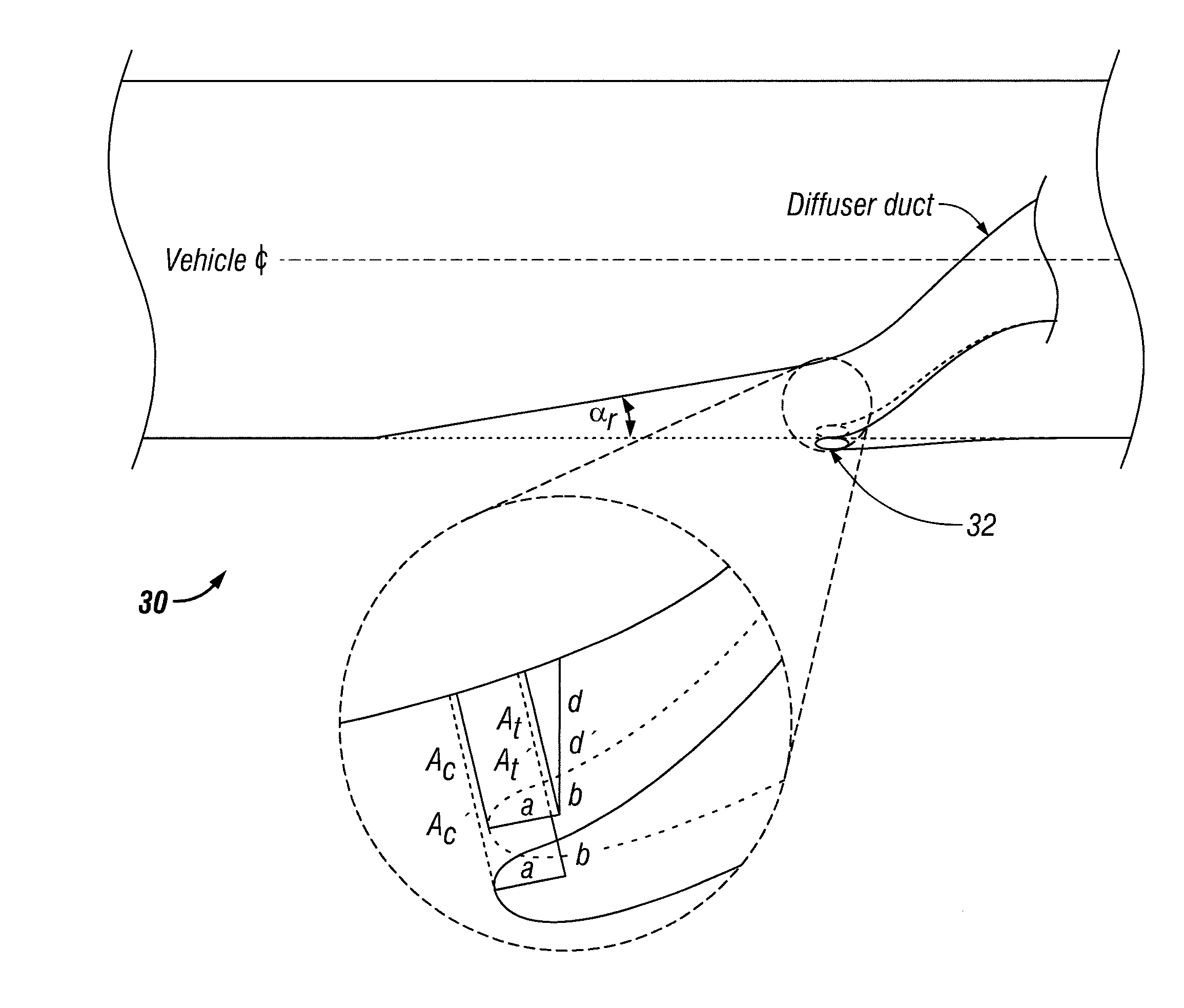
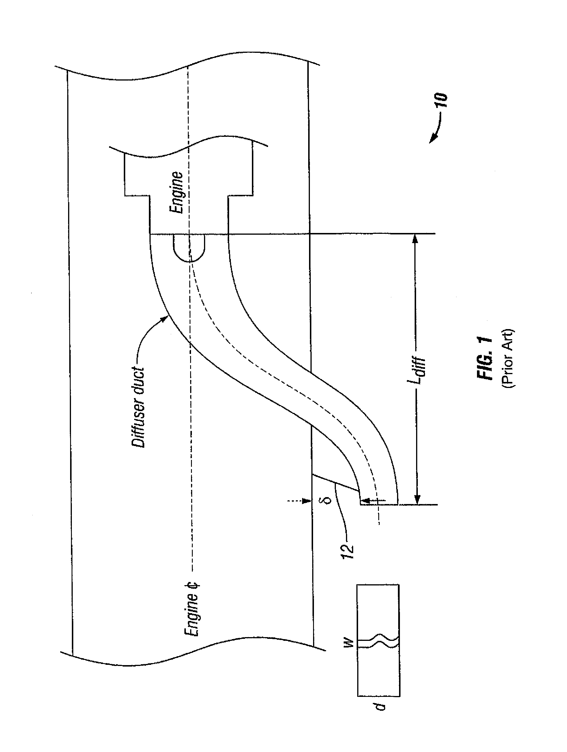
[0024]A hybrid air intake system in accordance with the present invention combines the best attributes of flush (submerged) inlets with the best attributes of pitot (scoop) inlets. The hybrid air intake system reduces the volume consumed by a flush inlet inside the airframe, while improving inlet aerodynamic performance (total pressure recovery and distortion levels), relative to its classical flush counterpart. The hybrid air intake system of the invention increases flush inlet capture and / or throat areas, without encroaching into the vehicle internal (fuel and / or payload) volume, improves inlet aerodynamic performance, retains the advantage of minimal protrusion from the fuselage, and approaches the performance of a scoop inlet.

[0025]The hybrid air intake system in accordance with the present invention retains the lower portion of the scoop inlet wall, including the cowl lip protruding from the fuselage. The hybrid air intake system also retains the sloping ramp with divergent sid...


PUM


Abstract

A hybrid air intake system and method for air-breathing missiles and aircraft comprising providing to an airborne vehicle fuselage an air intake opening comprising at least a pair of side walls and at least an upper wall and a lower wall extending between the side walls, wherein the lower wall extends below a plane defined by the vehicle fuselage, and not employing a boundary layer diverter between the fuselage and the upper wall.

Description

CROSS-REFERENCE TO RELATED APPLICATIONS[0001]This application claims priority to and the benefit of the filing of U.S. Provisional Patent Application Ser. No. 60 / 868,014, entitled “Air Intake System for Airborne Vehicles”, filed on Nov. 30, 2006, and the specification and claims thereof are incorporated herein by reference.STATEMENT REGARDING FEDERALLY SPONSORED RESEARCH OR DEVELOPMENT[0002]Not Applicable.INCORPORATION BY REFERENCE OF MATERIAL SUBMITTED ON A COMPACT DISC[0003]Not Applicable.COPYRIGHTED MATERIAL[0004]Not Applicable.BACKGROUND OF THE INVENTION[0005]1. Field of the Invention (Technical Field)[0006]The present invention relates to air intake systems for air-breathing missiles, aircraft, and the like.[0007]2. Description of Related Art[0008]Volume constraints inside an air breathing missile or aircraft, combined with high inlet performance demands (i.e., high levels of total pressure recoveries and low distortion levels at the engine face) makes the integration and packa...

Claims


Application Information

Patent Timeline
Patent Type & Authority Patents(United States)
IPC IPC(8): B64D33/02B64C21/02
CPCB64C21/02B64D33/02
Inventor RUIZ, CARLOS G.GEBERT, GLENN A.
Owner LOCKHEED MARTIN CORP
Why Eureka
Try Eureka