
Adaptive heating control system for a water heater

a control system and water heater technology, applied in control systems, testing/monitoring, heating types, etc., can solve the problems of user or device experiencing a sudden drop in water temperature, rapid increase in water demand, and water heating system presently available or prior art water heating system falling short, so as to reduce waste, reduce the delay in preparing, and reduce the effect of perceived demand

Active Publication Date: 2015-06-23
INTELLIHOT
View PDF10 Cites 21 Cited by
  • Summary
  • Abstract
  • Description
  • Claims
  • Application Information

AI Technical Summary

Benefits of technology

The present invention is a water heating control system that automatically reduces delay in delivering a volume of water at a desired temperature. The system uses historical and current flow demands to calculate a new flow demand, which is then exceeded if necessary to activate the system. The historical flow demand can be, for example, the average flow rate or the average frequency of user presence detection. The current flow demand is the current water flow rate (measured in gallons per minute) for at least 5 minutes. The system can be a device, such as a pump or a burner, or a combination of both. By preparing hot water based on present and historical usage, the system minimizes delay and reduces energy waste. It can be applied to various types of hot water heating devices and can be carried out in different ways.

Problems solved by technology

However, water heating systems presently available or prior art water heating systems fall short when attempting to maintain a water output at a constant predetermined temperature level during rapid shifts or fluctuations in water demand.
Placing predetermined water output temperature as a secondary consideration creates two major thermal related problems.
The first issue is encountered during a rapid increase in water demand, wherein the user or device experiences a sudden drop in water temperature or a cold water splash.
The remaining issue occurs during a rapid decrease in water demand, wherein the user or device experiences a sudden spike in water temperature, thereby creating a possible burn or scald type hazard.
Furthermore, none of the prior art water heaters are capable of delivering water at the predetermined or desired temperature range without substantial delays.
The rapid shifts in water demand creates a transient condition within the water heating system wherein such existing systems are ill equipped to handle.
The current on-demand water heaters have well known drawbacks, most notably, the uncontrollable and undesirable fluctuation of temperature of the output water during water usage.
This creates undesirable temperature fluctuations for users, appliances, and the like.
Disadvantages of these tankless water heaters are well known in the art and general population, such a discussion is described in Wikipedia, and reads as follows:Installing a tankless system comes at an increased cost, particularly in retro-fit applications.
They tend to be particularly expensive in areas such as the US where they are not dominant, compared to the established tank design.
If a storage water heater is being replaced with a tankless one, the size of the electrical wiring or gas pipeline may have to be increased to handle the load and the existing vent pipe may have to be replaced, possibly adding expense to the retrofit installation.
Thus there is a more apparent “flow delay” for hot water to reach a distant faucet.There is a short delay between the time when the water begins flowing and when the heater's flow detector activates the heating elements or gas burner.
However, for intermittent use applications (for example when a hot water faucet is turned on and off repeatedly) this can result in periods of hot water, then some small amount of cold water as the heater activates, followed quickly by hot water again.
This cold section of water takes some amount of time to reach the faucet and is dependent on the length of piping.Since a tankless water heater is inactive when hot water is not being used, they are incompatible with passive (convection-based) hot water recirculation systems.
They may be incompatible with active hot water recirculation systems and will certainly use more energy to constantly heat water within the piping, defeating one of a tankless water heater's primary advantages.Tankless water heaters often have minimum flow requirements before the heater is activated, and this can result in a gap between the cold water temperature, and the coolest warm water temperature that can be achieved with a hot and cold water mix.Similarly, unlike with a tank heater, the hot water temperature from a tankless heater is inversely proportional to the rate of the water flow—the faster the flow, the less time the water spends in the heating element being heated.
Also, when adjusting the mixture in mid-shower, the change in temperature will initially react as a tanked heater does, but this also will change the flow rate of hot water.
Power showers, for example, cannot be used with tankless systems because it cannot deliver the hot water at a fast enough flow-rate required by the pump.
The output water temperature experienced by both users dramatically decreases since the total flow rate through the water heater increases, and thus, the volume of water to be heated per unit of time has increased while the burner output remains constant (or the system is not capable of keeping pace with the increased water demand).
Other well known drawbacks associated current on demand water heaters include the cold sandwich effect, freeze hazards, and dead zones.
Controls for water heaters are plagued with limitations and lack the sophistication to maximize system efficiency.

Method used


Image

  • Adaptive heating control system for a water heater
  • Adaptive heating control system for a water heater
  • Adaptive heating control system for a water heater

Examples


Embodiment Construction

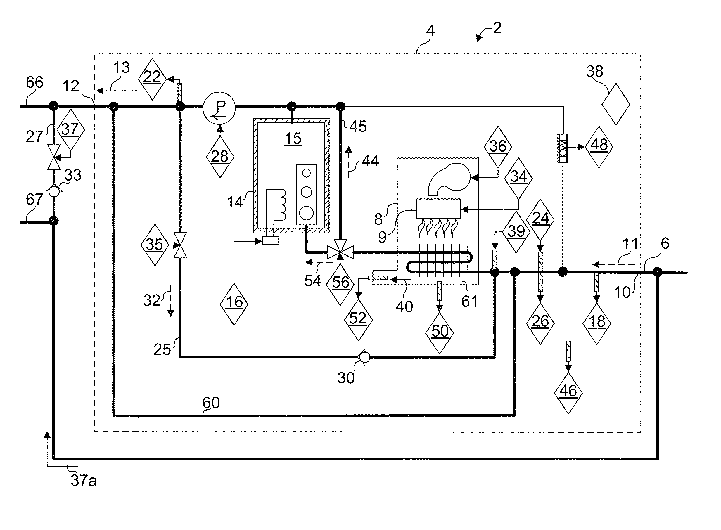
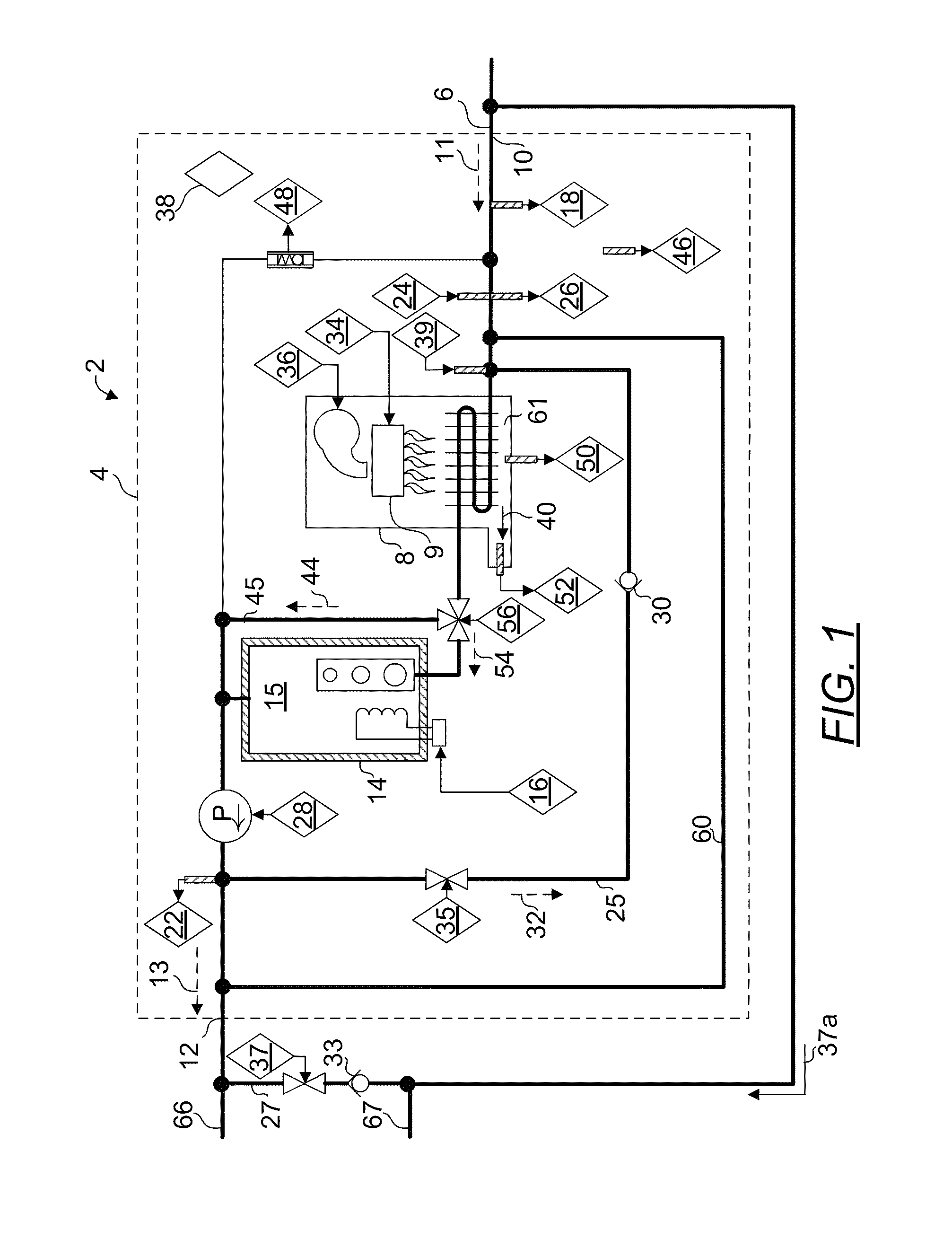
[0146]FIG. 1 illustrates one embodiment of a novel hybrid tankless water heater 2 (“water heater”) and the relative placement of various components of the system. Briefly described, the water heater 2 comprises an enclosure 4 having a thermally insulated mixing buffer tank 15 with baffles disposed downstream from a heat exchanger of a primary heating system 8. There is further provided a secondary heating element 16 to supply supplemental heat, preferably disposed in mixing buffer tank 15. The combination of two heating systems (such as gas and immersion electric) thus renders the present invention a “hybrid” water heater.

[0147]Optionally there is further provided a differential pressure switch 48 that functions to rapidly detect a need to turn on primary 8 or secondary 16 heating elements by detecting trickle or low flow. There is also provided an internal recirculating system 25 and an inverted burner system in primary heating system 8. The differential pressure switch is an impor...


PUM


Abstract

A water heating control system for automatically reducing delay in delivering a volume of water at a flowrate, the volume of water is heated from a first temperature to a target temperature during a time interval of a day, the water heating system includes a device for aiding in heating the volume of water from the first temperature to the target temperature, a historical flow demand corresponding to the time interval of a day, a current flow demand corresponding to the time interval of a day and a controller configured for calculating a new flow demand from the historical flow demand and the current flow demand. The new flow demand is set as the historical flow demand for the time interval of a day and if the new flow demand exceeds a threshold, the device is configured to be activated during the time interval of a day.

Description

FIELD OF INVENTION[0001]This invention relates to a control system for water heaters, and more specifically, to an adaptive control system for water heaters based on the present and historical usage of hot water.BACKGROUND ART[0002]Most water heaters are capable of delivering water at a desired temperature in steady state conditions where the water demand or flow rate is substantially constant. However, water heating systems presently available or prior art water heating systems fall short when attempting to maintain a water output at a constant predetermined temperature level during rapid shifts or fluctuations in water demand. It is understood that the demand for water is directly related to the output flow rate requested from the water heating system. Prior art water heating systems will provide the water output flow rate corresponding to the water demand placing the predetermined temperature setting as a secondary consideration. Placing predetermined water output temperature as ...

Claims


Application Information

Patent Timeline
Patent Type & Authority Patents(United States)
IPC IPC(8): G06F19/00G05D7/06G05B23/02
CPCG05D7/0629G05B23/0235G05D23/1904F24D17/0036F24D17/0073F24D17/0078F24D19/1051F24D2200/04F24D2200/08F24D2220/042Y02B10/20Y02B10/70F24H15/395F24H15/104F24H15/34F24H15/421F24H15/172F24H15/35F24H15/144F24H15/242F24H15/281F24H15/12F24H15/265F24H15/31F24H15/20F24H15/37F24H15/219F24H15/325F24H15/235F24H15/215F24H15/174F24H15/238F24H15/128
Inventor DEIVASIGAMANI, SRIDHARAKASAM, SIVAPRASAD
Owner INTELLIHOT
Learn More