Methods and systems for a distributed radio communications network

a radio communication network and method technology, applied in the field of methods and systems for a distributed radio communication network, can solve the problems of complex receiving functions and costly processing systems, and achieve the effects of improving communication link margin, improving maintenance and update, and low cos

Active Publication Date: 2015-06-23
COGNOSOS
View PDF19 Cites 14 Cited by
  • Summary
  • Abstract
  • Description
  • Claims
  • Application Information

AI Technical Summary

Benefits of technology

[0004]In some aspects, and as disclosed herein, certain SDR features may be centralized at, or selectively-assigned to, and / or delegated to particular devices operating in a distributed radio communications network. In certain embodiments, updates to particular SDR functions may be directed to a central device (or devices) hosting the SDR functions, instead of being distributed to disparate locations via a network. Such updates may be transmitted through the network, and in some cases wirelessly. Such SDR configurations may allow for more manageable maintenance and update, for example, as compared to dedicated hardware or installation of full-featured SDRs at every node. The present disclosure also describes systems and methods which address impairments such as doppler and multipath associated with ionospheric propagation, and may improve communication link margin by combining data received at multiple locations.
[0008]In some embodiments, at least one of the first gateway and the second gateway may receive one of the RF signals reflected off of the ionosphere. The first gateway and the second gateway may receive the modulated signals as RF signals transmitted via at least two of: a direct path from the first node, a ground wave path, and ionospheric reflection. The first node may transmit a low-power, RF signal between 3 and 30 megahertz (MHz), over a transmission path of more than 10 kilometers to at least one of the first gateway and the second gateway. The server may time-synchronize the modulated signals separately received from the first gateway and the second gateway for combination of the modulated signals. The server may identify and may remove interfering signals from the modulated signals received from the first gateway and the second gateway.

Problems solved by technology

This could occur when the complexity of some receiving functions require costly processing systems (for example MIMO / MISO / SIMO applications).

Method used


Image

  • Methods and systems for a distributed radio communications network
  • Methods and systems for a distributed radio communications network
  • Methods and systems for a distributed radio communications network

Examples


Embodiment Construction

[0024]For purposes of reading the description of the various embodiments below, the following descriptions of the sections of the specification and their respective contents may be helpful:[0025]Section A describes a network environment and computing environment which may be useful for practicing embodiments described herein; and[0026]Section B describes embodiments of methods and apparatuses for a distributed radio communications network.

A. Computing and Network Environment

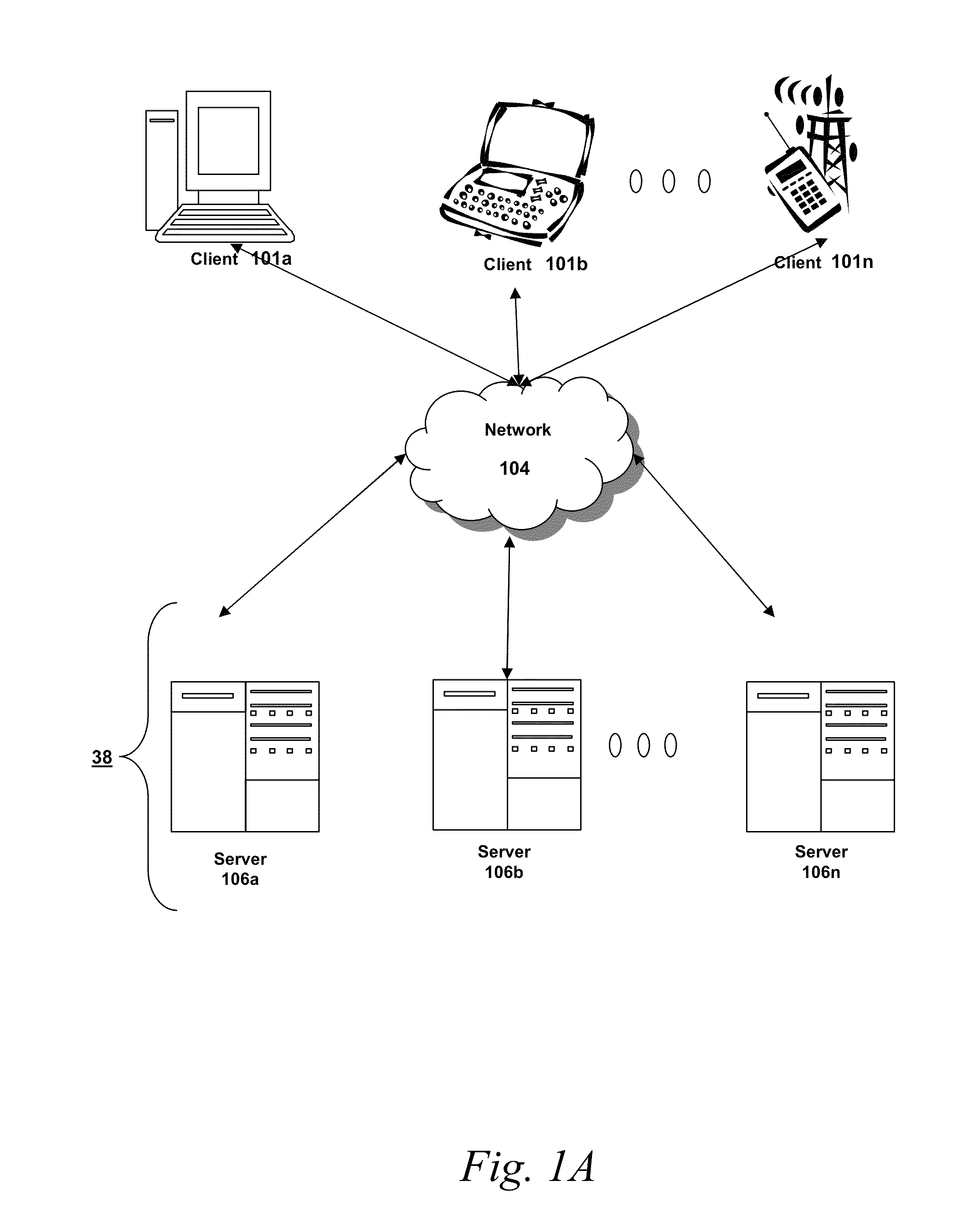
[0027]Prior to discussing specific embodiments of the present solution, it may be helpful to describe aspects of the operating environment as well as associated system components (e.g., hardware elements) in connection with the methods and systems described herein. Referring to FIG. 1A, an embodiment of a network environment is depicted. In brief overview, the network environment includes one or more clients 101a-101n (also generally referred to as local machine(s) 101, client(s) 101, client node(s) 101, client m...


PUM


Abstract

The present disclosure is directed to methods and systems for providing a distributed radio communications network. Each of a first gateway and a second gateway may separately receive modulated signals comprising at least a portion of data from a first node of a plurality of geographically-dispersed nodes. The modulated signals may be wirelessly transmitted as radio frequency (RF) signals from the first node, the data gathered or generated by the first node at a first location. A server may receive the modulated signals from the first gateway and the second gateway. As configured by software-defined radio (SDR) software, the server may perform processing of the separately received modulated signals to recover the data. The processing may include demodulation of the modulated signals.

Description

FIELD OF THE DISCLOSURE[0001]This disclosure generally relates to methods and systems for distributed collection of data. In particular, this disclosure relates to methods and systems for a distributed radio communications network.BACKGROUND OF THE DISCLOSURE[0002]Conventional data collection networks, such as wireless sensor networks (WSNs), provides distributed monitoring using sensor nodes which typically aim to be low-cost and / or low-power. The geographical range of such networks may be limited and certain networks may employ multi-hop transmission over a number of nodes, such as in a mesh configuration. Some data collection systems sometimes face network impairment due to disabled nodes and / or low signal-to-noise ratios. Certain conventional data collection networks also face increased costs due to the number of nodes deployed to support the network, specialized hardware to gather or process the data, and / or maintenance / upgrade of these remote nodes. In multiple industries incl...

Claims


Application Information

Patent Timeline
Patent Type & Authority Patents(United States)
IPC IPC(8): H04W84/18H04W92/14H04W24/00H04W84/02H04L27/06H04W56/00
CPCH04L27/06H04W84/18H04B1/0003H04B7/22H04B7/022H04B7/0885H04W88/16
Inventor STRATIGOS, JR., JAMES A.
Owner COGNOSOS
Why Eureka
Try Eureka