Compressible and expandable blade for a fluid pump

a fluid pump and expandable technology, applied in the field of mechanical or micromechanics, can solve the problems of restricted subdividence, and achieve the effects of simple and economical production, increased external resistance, and high compressibility

Active Publication Date: 2015-06-30
ECP ENTWICKLUNGSGMBH
View PDF237 Cites 28 Cited by
  • Summary
  • Abstract
  • Description
  • Claims
  • Application Information

AI Technical Summary

Benefits of technology

[0008]With the background of the state of the art, the object underlying the present invention is to produce a rotor which can be produced as simply and economically as possible or a blade for such a rotor, high compressibility being paramount with as little as possible of a force expenditure so that, in order to withdraw the pump from the vessel, the compression of the pump rotor can be achieved without greater external resistances. In addition, the corresponding pump is intended to be designed to be efficient and low-consumption.

Problems solved by technology

However, the ability to be subdivided is restricted by the intrinsic stability of the partial blades which requires to be ensured.

Method used


Image

  • Compressible and expandable blade for a fluid pump
  • Compressible and expandable blade for a fluid pump
  • Compressible and expandable blade for a fluid pump

Examples


Embodiment Construction

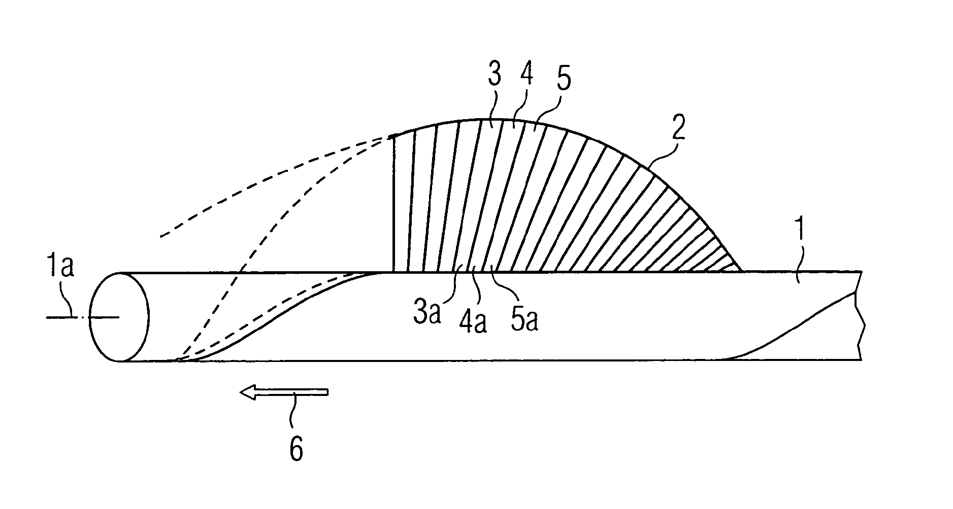
[0061]FIG. 1 shows a rotor shaft 1 having a blade 2 which is composed of individual, schematically indicated lamellae 3, 4, 5. The individual lamellae are mounted pivotably respectively by their feet 3a, 4a, 5a on the rotor shaft 1, the feet of the lamellae together extending around the rotor shaft 1 in a spiral.

[0062]In this way, a helical structure of a blade is produced, which effects an axial conveyance of a liquid in the direction of the arrow 6 during rotation about the rotor shaft 1.

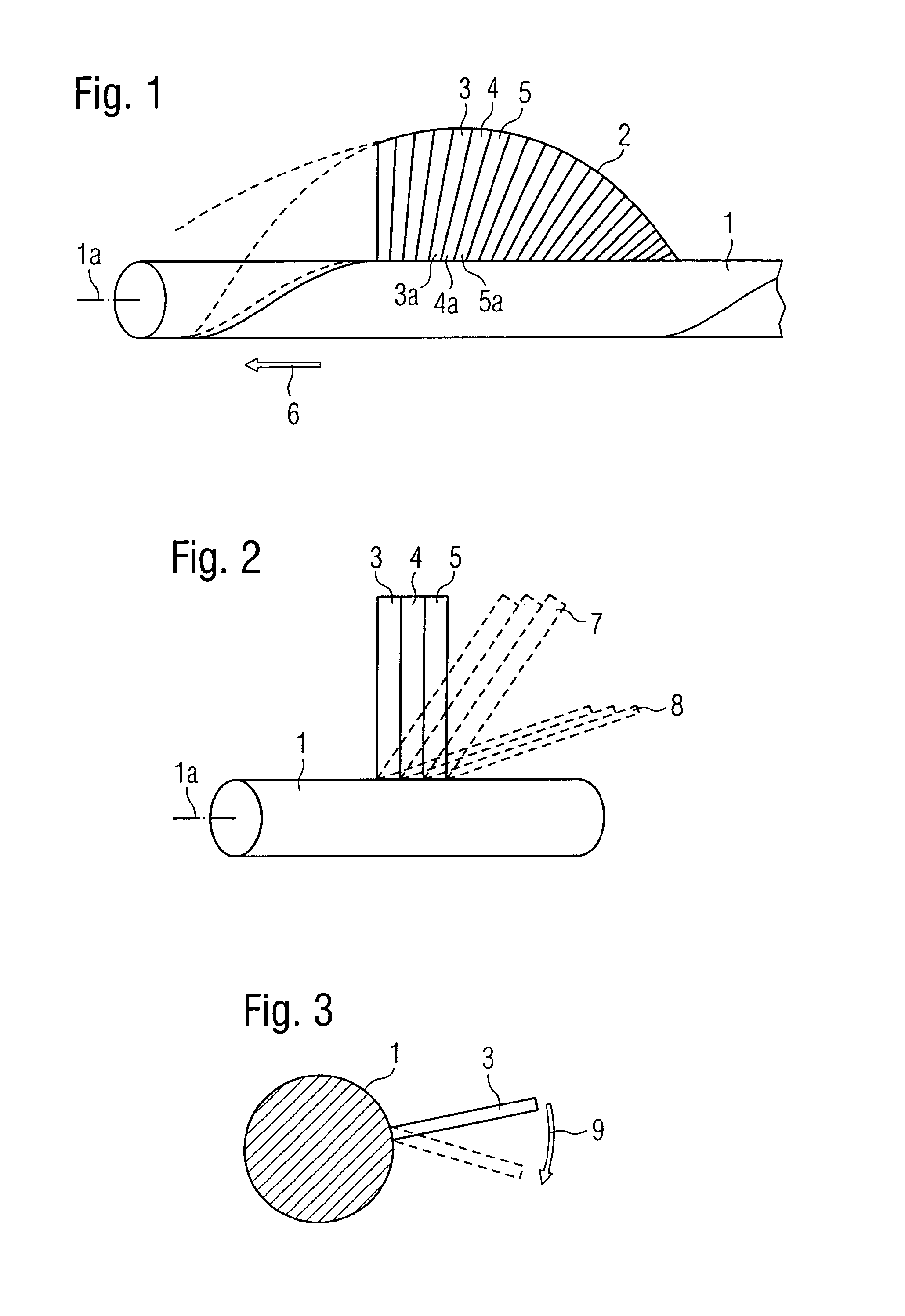
[0063]The particular embodiment of the blade according to the invention emerges in more detail from FIG. 2. In a first position, the lamellae 3, 4, 5 are represented there in the deployed, expanded shape of the blade, the adjacent lamellae abutting closely against each other by their longitudinal sides and hence forming a surface which is smooth and sealed for the flowing fluid.

[0064]In the position which is illustrated in broken lines and designated with 7, the individual lamellae are folded a li...


PUM

PropertyMeasurementUnit
diameteraaaaaaaaaa
diameteraaaaaaaaaa
thicknessaaaaaaaaaa

Abstract

The invention relates to a compressible and expandable blade for the rotor of a fluid pump having at least two lamellae which are disposed adjacently, are pivotable respectively relative to an axis of rotation of the rotor and moveable relative to each other, and abut against each other in the expanded state of the blade such that they form together a continuous blade surface.

Description

BACKGROUND OF THE INVENTION[0001]The present invention resides in the field of mechanics or micromechanics and can be applied advantageously in particular in medical technology.[0002]The invention relates to a blade for a pump and the design thereof. Of concern thereby is a pump having a rotor, the rotor being compressible and expandable in order to be able possibly to change the overall dimensions of the pump. In this way, the pump can be pushed through not readily accessible openings or into narrow pipe systems, for which purpose it is firstly compressed and, after it has been moved to the location of use, is expanded again.[0003]Such a pump can be used particularly advantageously in medical technology in the field of heart pumps or other pumps for body fluids which are normally used with catheters.[0004]In the technical medical field, different types of micropumps are known, which pumps can be introduced in the compressed state with a catheter through a naturally occurring body v...

Claims


Application Information

Patent Timeline
Patent Type & Authority Patents(United States)
IPC IPC(8): A61M1/00F04D3/00A61M1/10A61M1/12F04D29/24F04D29/18A61M60/13A61M60/174A61M60/237A61M60/808
CPCA61M1/101A61M1/12F04D3/00F04D29/181F04D29/247A61M1/1024A61M1/125Y10T29/49337A61M60/414A61M60/148A61M60/808A61M60/174A61M60/237A61M60/13A61M60/122A61M60/135A61M60/857A61M60/205B23K26/21A61M2207/00B23H9/10B23K26/38F04D3/02F04D15/0055
Inventor TOELLNER, THOMAS
Owner ECP ENTWICKLUNGSGMBH
Why Eureka
Try Eureka