
All graphite interferometer bearing assembly

a technology of interferometer and bearings, which is applied in the direction of optical radiation measurement, instruments, spectrometry/spectrometry/monochromators, etc., can solve the problems of limiting the stroke length and system resolution, mechanical pivot-type bearings can have errors in mirror alignment, and the weight of air bearings is high, so as to reduce the weight of the assembly and reduce the cost. , the effect of low power control system

Active Publication Date: 2015-06-30
THERMO ELECTRONICS SCI INSTR LLC
View PDF3 Cites 5 Cited by
  • Summary
  • Abstract
  • Description
  • Claims
  • Application Information

AI Technical Summary

Benefits of technology

The all-graphite bearing assembly provides precise mirror alignment control, long stroke lengths, excellent vibration damping, and reduced sensitivity to external vibrations, enabling high-speed scanning and cost-effective, reliable operation.

Problems solved by technology

Moreover, the mobile mirror is also often part of an assembly that includes either air bearings or mechanical pivot-type bearings which require costly close tolerance machining and assembly for controlling the tilt of the movable mirror as it moves.
Air bearings offer higher performance but are expensive and require an air compressor and filter to supply compressed air.
Mechanical pivot-type bearings can have errors in the mirror alignment as the mirror moves.
Such alignment problems worsen at long stroke lengths, thus limiting the stroke length and system resolution.
Moreover, these types of bearings are subject to wear and degradation.
In addition, mechanical bearings also have poor damping and tend to capture or generate mechanical and acoustical vibrations, thereby causing noise in the system output data.
However, such assemblies have inherent problems in manufacturing and reliability.
For example, current manufacturing processes for such glass / graphite configurations calls for hand fitting of the glass tube to the piston, which often leads to large variances between batches of parts.
Another problem encountered with such assemblies is that surface imperfections in the glass tube often result in tilt and drive jitter during operation of the final assembly in the interferometer.
Finally, buildup of friction of the graphite piston, as evidenced by graphite dust in the glass tube, resulted in the need for higher drive voltages to be applied and such buildup eventually causes system downtime based on the need to clean the glass tube and graphite piston periodically.

Method used


Image

  • All graphite interferometer bearing assembly
  • All graphite interferometer bearing assembly
  • All graphite interferometer bearing assembly

Examples


Embodiment Construction

[0014]In the description of the invention herein, it is understood that a word appearing in the singular encompasses its plural counterpart, and a word appearing in the plural encompasses its singular counterpart, unless implicitly or explicitly understood or stated otherwise. Furthermore, it is understood that for any given component or embodiment described herein, any of the possible candidates or alternatives listed for that component may generally be used individually or in combination with one another, unless implicitly or explicitly understood or stated otherwise. Moreover, it is to be appreciated that the figures, as shown herein, are not necessarily drawn to scale, wherein some of the elements may be drawn merely for clarity of the invention. Also, reference numerals may be repeated among the various figures to show corresponding or analogous elements. Additionally, it will be understood that any list of such candidates or alternatives is merely illustrative, not limiting, u...


PUM

PropertyMeasurementUnit
densityaaaaaaaaaa
sizesaaaaaaaaaa
reflectivityaaaaaaaaaa

Abstract

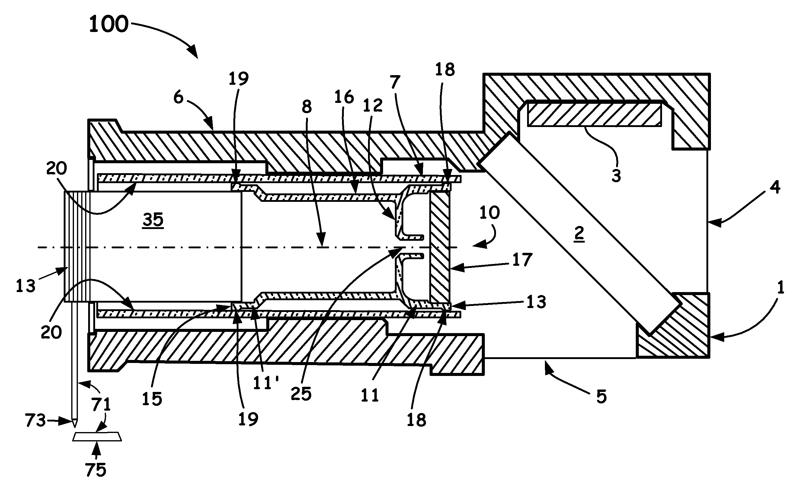
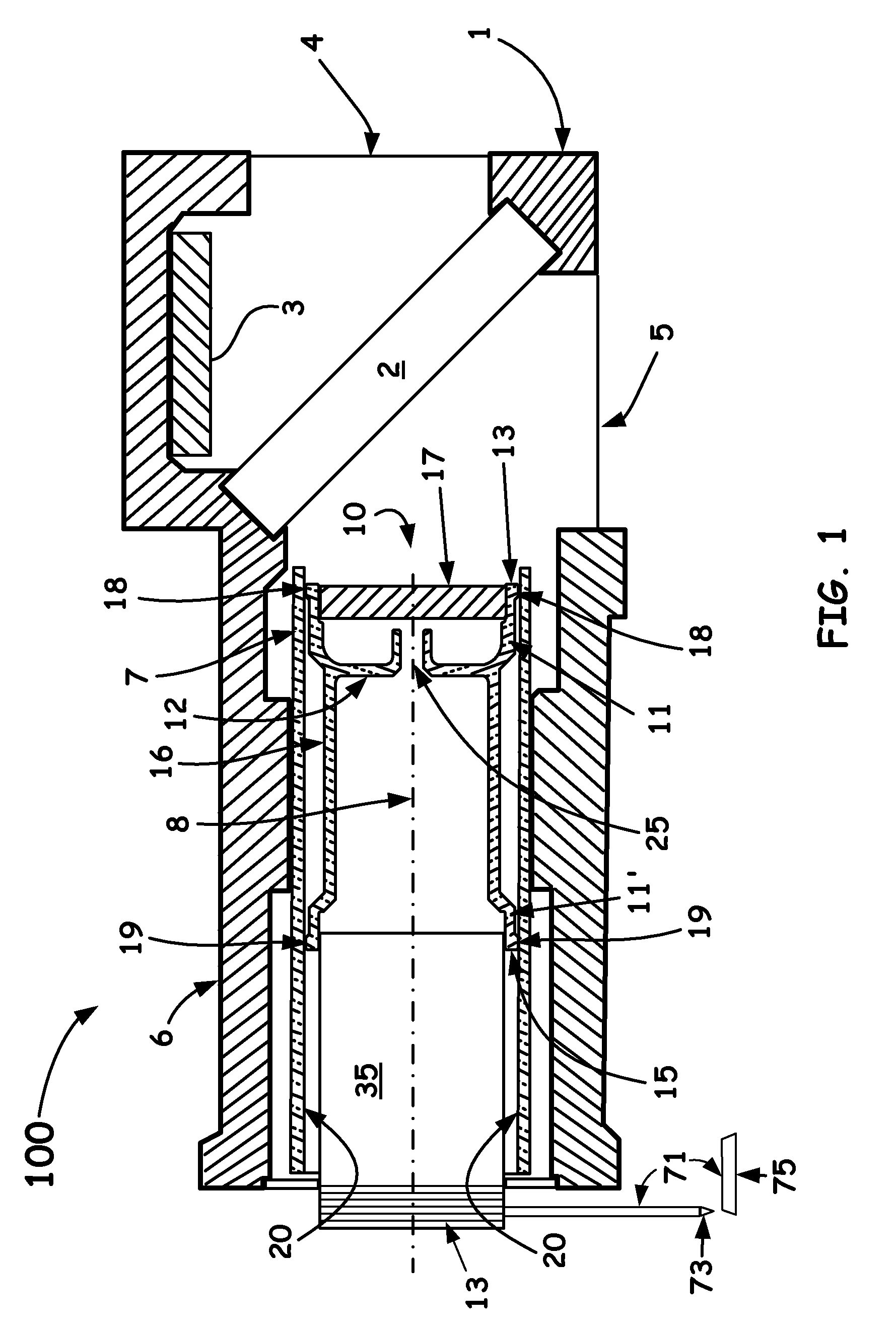
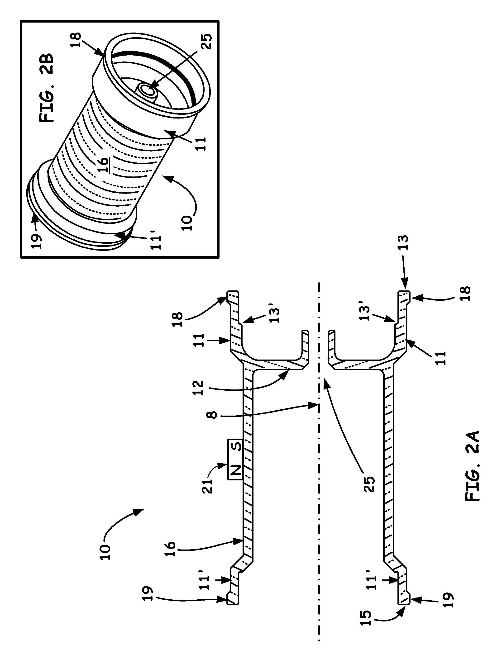
An all-graphite interferometer bearing assembly is introduced that allows the movement of a movable mirror in a Michelson interferometer without degradation during use. The assembly includes a stationary hollow graphite tube and a movable assembly which includes a mirror and a monolithic graphite member slidably disposed within the bore of the graphite tube that is composed of the same grade of graphite material as the monolithic graphite member. The result is a robust novel moving mirror arrangement in a Michelson interferometer that enables precise mirror alignment control, a long stroke length, excellent vibration damping and reduced sensitivity to external vibrations.

Description

BACKGROUND OF THE INVENTION[0001]1. Field of the Invention[0002]The present invention relates to the field of optical scientific instrumentation. More specifically, the present invention relates to an all-graphite bearing assembly as part of a Michelson interferometer.[0003]2. Discussion of the Related Art[0004]An optical interferometer used in a scientific analytical instrument relies on the interference of superimposed optical beams as part of the interrogation means. When configured as a Michelson Fourier-Transformed infrared (FTIR) instrument, the optical output of the interferometer is called an interferogram. The FTIR interferometer itself often includes a beam splitter and two mirrors, one that is conventionally stationary, and one which is conventionally mobile. The mobile mirror moves along the optic axis while staying optically perpendicular to the light beam at all times. The movement of the mobile mirror is often desired to be feedback-controlled in order to hold the mir...

Claims


Application Information

Patent Timeline
Patent Type & Authority Patents(United States)
IPC IPC(8): F16C29/02F16C33/16G01J3/02G01J3/06G01J3/453
CPCF16C33/16F16C29/02G01J3/0202G01J3/06G01J3/4535
Inventor IVERSON, JOHN R.
Owner THERMO ELECTRONICS SCI INSTR LLC
Learn More