Threaded connection

a threaded connection and threaded technology, applied in the direction of screw threaded joints, pipe elements, closures, etc., can solve the problems of insufficient robustness of the threaded connection in day-to-day operations, the service life of such thread shapes has proved too short in the daily operation of trench-work apparatuses, and the threaded connection disclosed in de 198 03 304 a1 has not been sufficiently robust. , to achieve the effect of improving the stress distribution in

Active Publication Date: 2015-07-14
TRACTO TECHN
View PDF46 Cites 0 Cited by
  • Summary
  • Abstract
  • Description
  • Claims
  • Application Information

AI Technical Summary

Benefits of technology

[0023]In another preferred embodiment of the present invention, the root of the thread of the interior thread of the threaded bushing furthermore forms a segment of a horizontal ellipse. This can further improve the stress distribution in the root of the interior thread of the threaded bushing.
[0024]To allow the threaded plug to be easily and quickly screwed into the threaded bushing of the threaded connection according to the invention, the exterior thread of the threaded plug and optionally also th

Problems solved by technology

However, a substantial disadvantage of threaded connection is that they frequently represent the weakest points of the rod assembly, caused by the relatively small diameter in the region of the threaded plug of the threaded connection as well as the geometry-related high stress concentration fatigue of the thread itself.
However, the service life of such thread shapes has proven to b

Method used


Image

  • Threaded connection
  • Threaded connection
  • Threaded connection

Examples


first embodiment

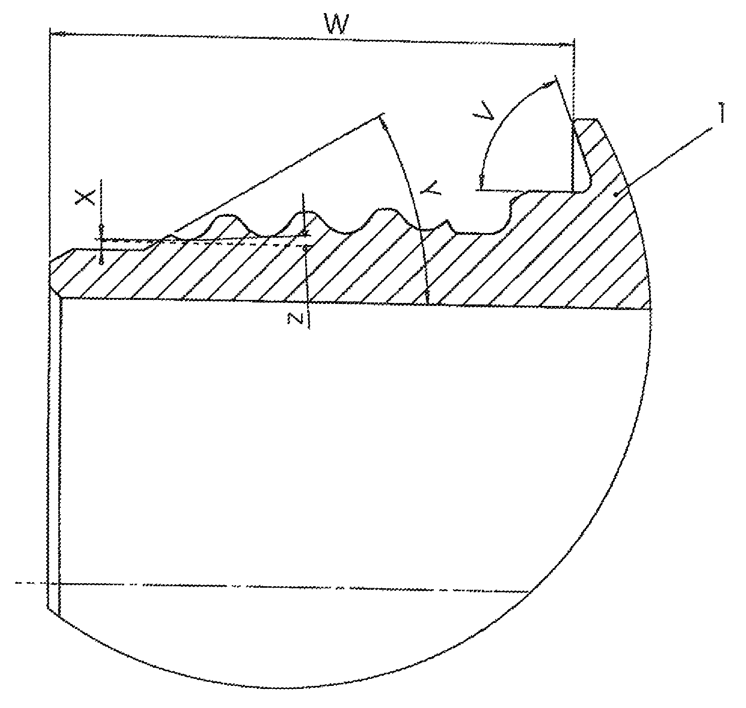
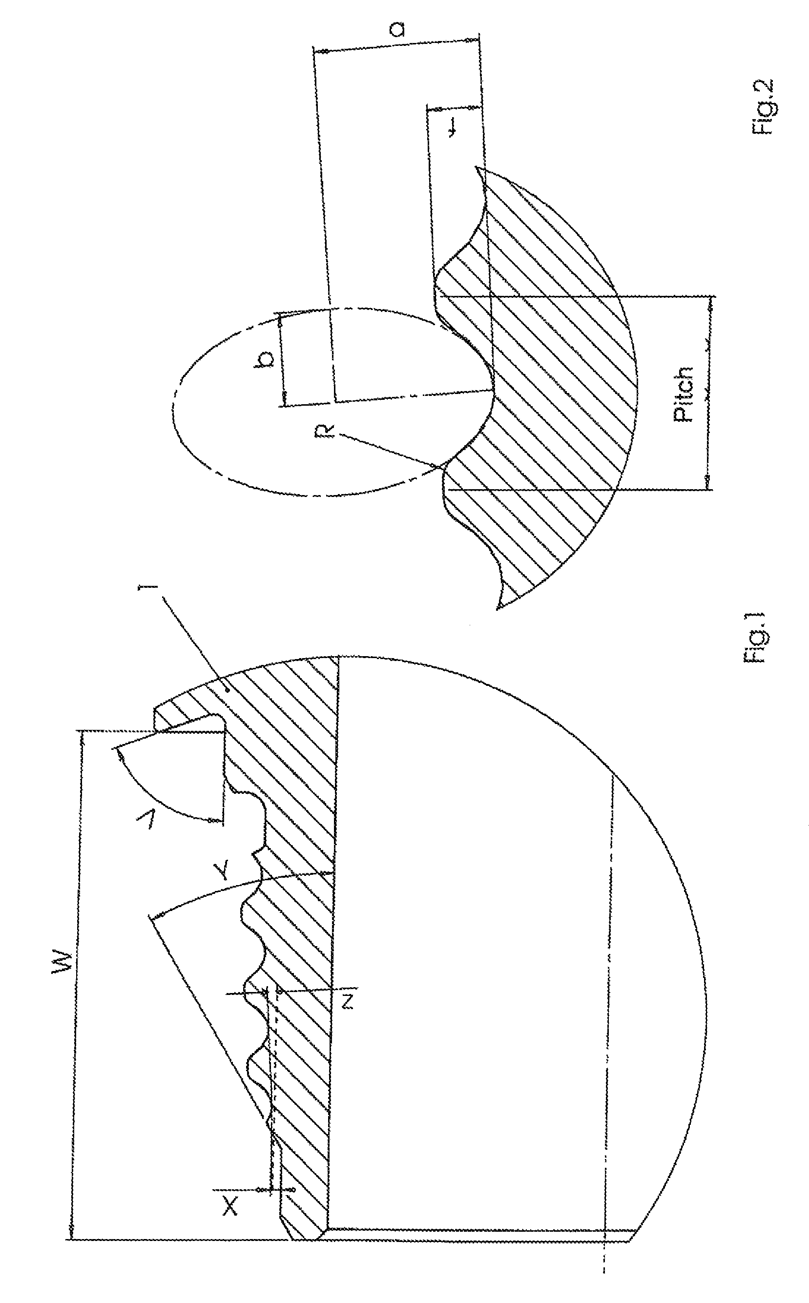
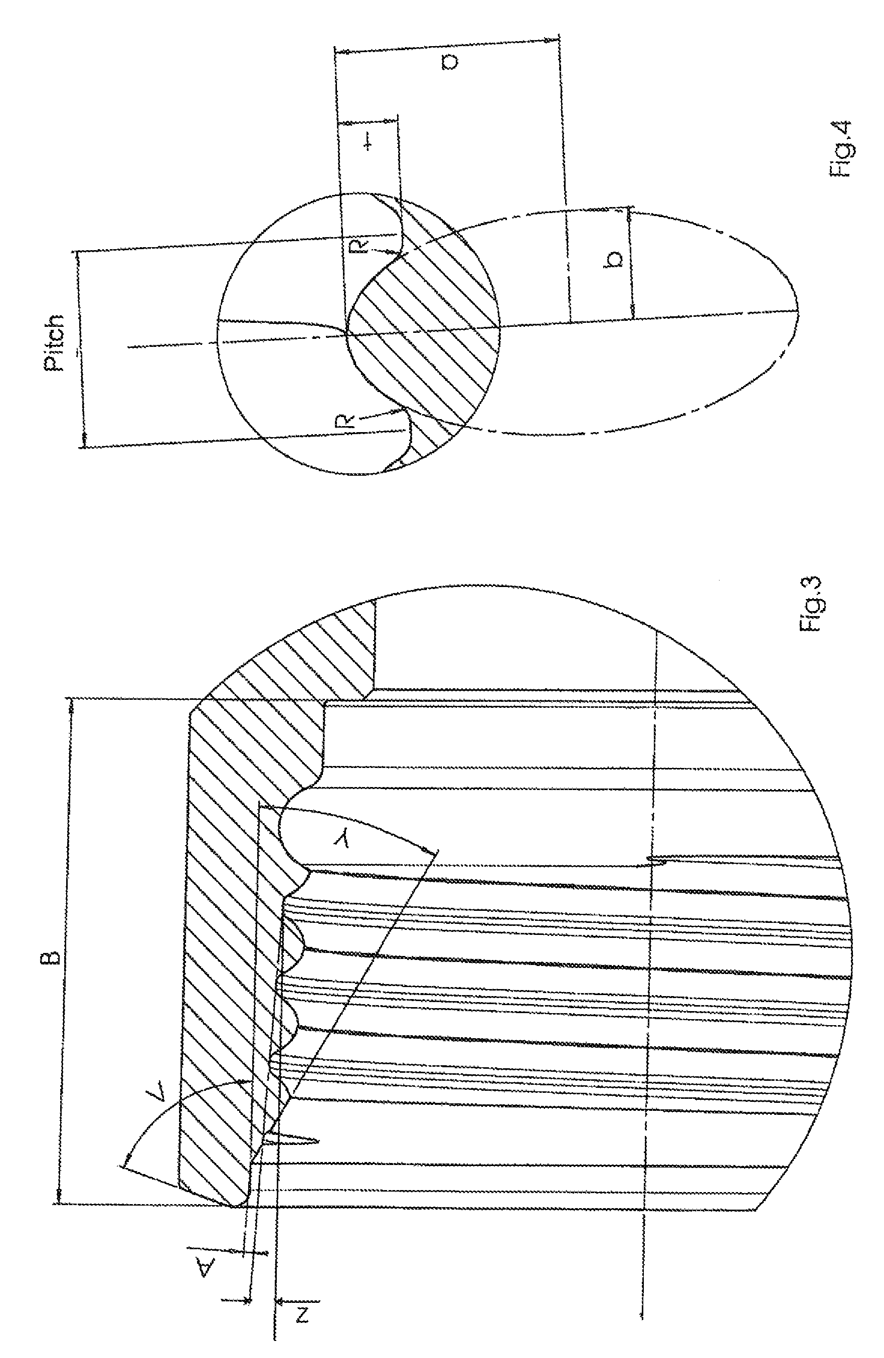
[0048]FIGS. 1 to 4 illustrate a threaded connection according to the invention. The threaded plug of the invention (FIG. 1) of this threaded connection is formed as an exterior thread on an end of a hollow rod the section 1 of a rod assembly of a trench-work apparatus. The exterior thread of the threaded plug is formed as a conical thread, i.e., the extension of the envelope defined by the individual roots of the thread intersects the longitudinal axis of the threaded plug at an angle (Z) of preferably between 3° and 5°. The corresponding mating interior thread of the threaded bushing (FIG. 3) has a matching cone angle (Z).

[0049]As indicated in particular in FIG. 2, both flanks as well as the root of the thread of a turn are formed as segments of one and the same ellipse. The crests of the thread are rounded on both sides with a radius (R). The pitch of the thread is defined by the spacing between two adjacent thread profiles or roots and is in the present example twice the length (...

second embodiment

[0054]FIGS. 5 to 7 illustrate a threaded connection according to the invention. As a particular characteristic of this threaded connection, the roots of the threads of the threaded bushing additionally also form a segment of an ellipse, in this case horizontal ellipse. This design can further improve the distribution of the stresses to which the interior thread of the threaded bushing is subjected. It has been observed that in the illustrated threaded connection the flat-topped crests of the threads of the threaded plug do not make direct contact with the roots of the threads of the threaded bushing in the screwed-together configuration.

[0055]In the following, the flank angle and the curvature of the ellipse of a threaded connection according to the invention are calculated with reference to an example. The geometric relationships are shown in the illustration in FIG. 8.

[0056]Geometric⁢⁢data⁢⁢ellipse⁢:a:=8⁢⁢b:=4Thread⁢⁢depth⁢:t:=2

[0057]The end of the counter loop is determined by th...


PUM


Abstract

A threaded plug for a threaded connection includes a core having an exterior thread. At least one flank of the exterior thread forms a segment of an ellipse, wherein the segment of the ellipse extends continuously from a root of the thread to a corresponding crest of the thread. A threaded connection can be formed by combining the threaded plug with a threaded bushing having an interior thread constructed to engage with the exterior thread of the threaded plug.

Description

CROSS-REFERENCES TO RELATED APPLICATIONS[0001]This application is the U.S. National Stage of International Application No. PCT / EP2009 / 006519, filed Sep. 8, 2009, which designated the United States and has been published as International Publication No. WO 2010 / 028809 and which claims the priority of German Patent Application, Serial No. 10 2008 047 060.0, filed Sep. 12, 2008, pursuant to 35 U.S.C. 119(a)-(d).BACKGROUND OF THE INVENTION[0002]The invention relates to a threaded connection and more particularly to a threaded connection for a rod assembly made of rod sections of a trench-work apparatus.[0003]The term “trench-work apparatus” within the context of the invention refers to apparatuses configured to transmit drive power from a drive apparatus via a rod assembly to a tool arranged on the rod assembly. These include in particular ground-boring machines used to introduce ground boreholes and in particular horizontal boreholes in the ground. Typically, the drive apparatus transm...

Claims


Application Information

Patent Timeline
IPC IPC(8): F16L55/10F16L15/06B65D59/06E21B17/042
CPCE21B17/042E21B17/0426F16L15/06
Inventor KOCH, ELMARWURM, DIETERHOMRINGHAUS, ROUWENFISCHER, SEBASTIAN
Owner TRACTO TECHN
Why Eureka
Try Eureka