Electrode having gas discharge function and plasma processing apparatus
a technology of plasma processing apparatus and electrode, which is applied in the direction of discharge tube/lamp details, discharge tube main electrodes, discharge tube materials, etc., can solve the problems of gas hole at the processing space damage, limited degree of freedom related to the maximum gas flow rate, and inability to reduce manufacturing costs
- Summary
- Abstract
- Description
- Claims
- Application Information
AI Technical Summary
Benefits of technology
Problems solved by technology
Method used
Image
Examples
first embodiment
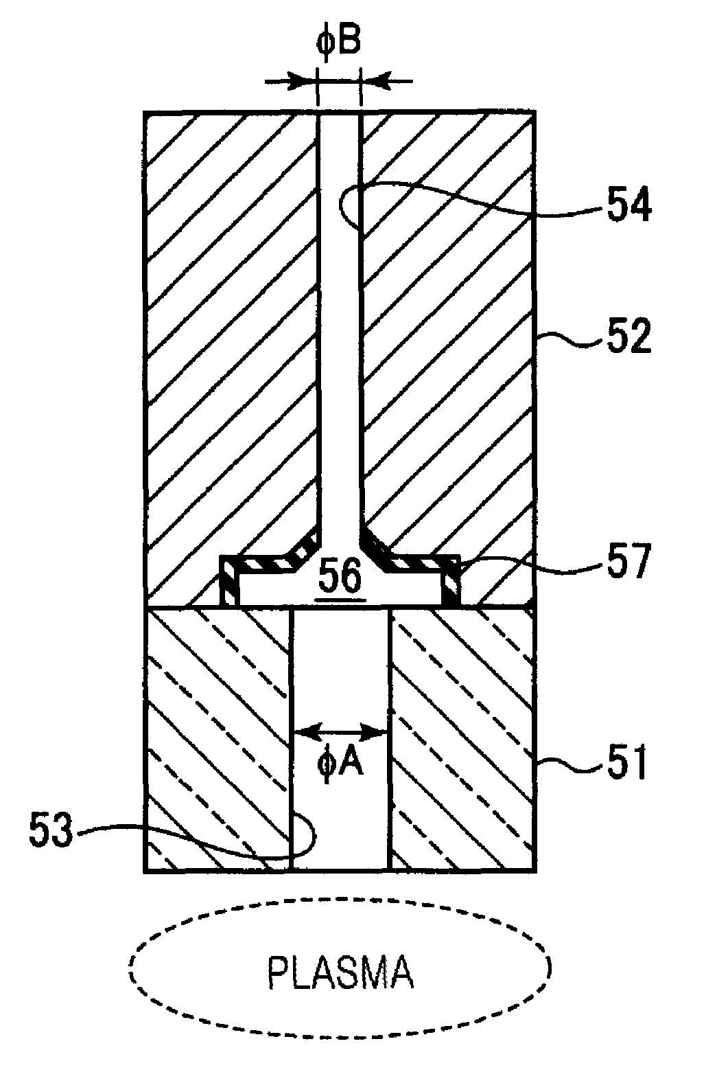
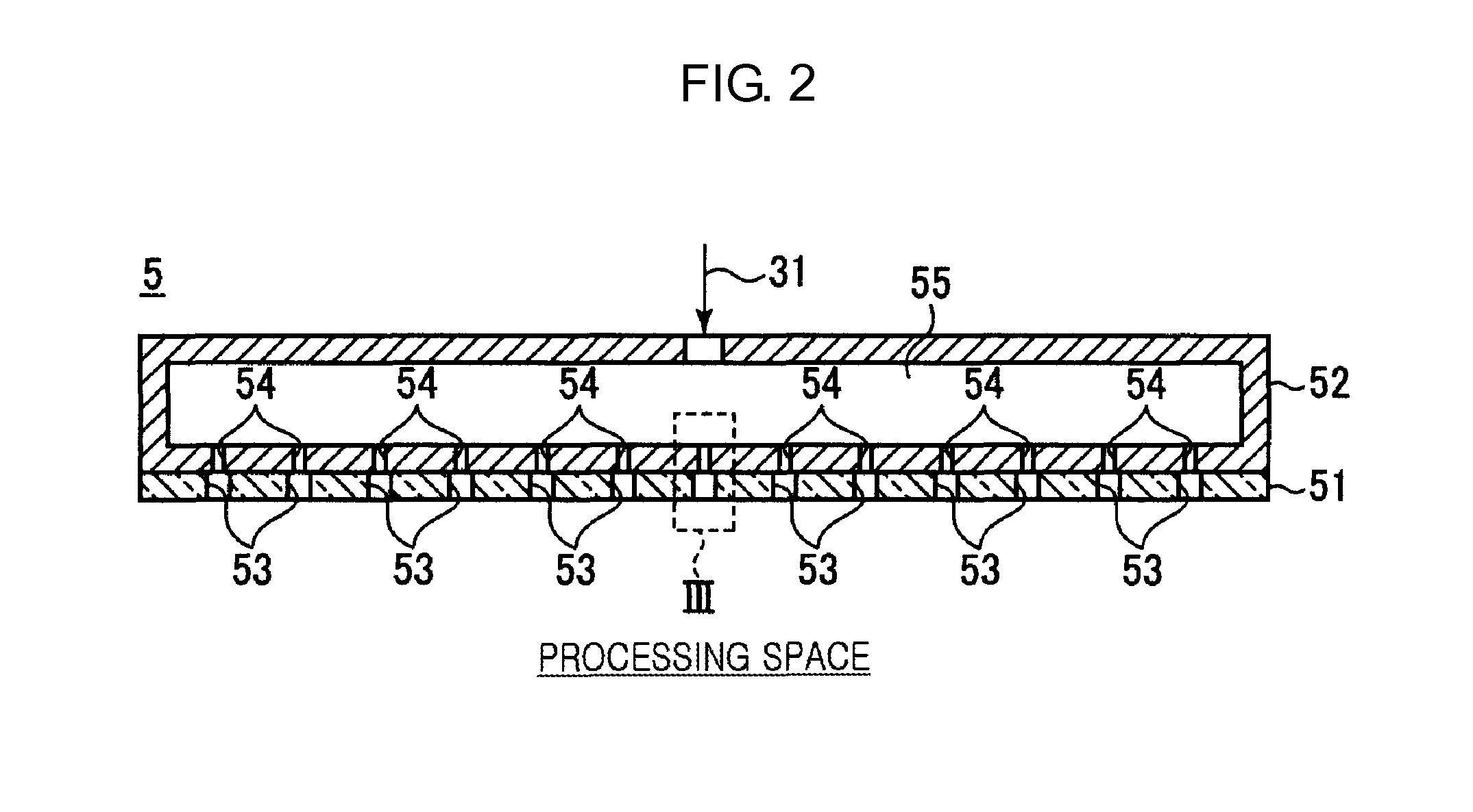
[0052]FIG. 3 is a magnified view of an example of an inside of a broken line frame III of FIG. 2, according to a first embodiment of an electrode having a gas discharge function.
[0053]As shown in FIG. 3, in the present embodiment, a gas hole diameter φA of the gas hole 53 of the electrode cover member 51 is larger than a gas hole diameter φB of the gas hole 54 of the base material 52. For example, the gas hole diameter φA exceeds the gas hole diameter φB and less than or equal to three times of the gas hole diameter φB.
[0054]The reason why the gas hole diameter φA exceeds the gas hole diameter φB is to increase conductance of the gas hole 53 of the electrode cover member 51 higher than conductance of the gas hole 54 of the base material 52. As such, by setting the conductance of the gas hole 53 of the electrode cover member 51 higher than the conductance of the gas hole 54 of the base material 52, a differential pressure (stress) due to the processing gas is not applied to the elect...
second embodiment
[0062]FIG. 4 is a magnified view of an example of the inside of the broken line frame III of FIG. 2, according to a second embodiment of an electrode having a gas discharge function.
[0063]The coating film 57 may be formed throughout a side wall from a bottom of the clearance portion 56 having the concave shape as shown in FIG. 3, or may be formed only at the bottom of the clearance portion 56 having the concave shape as shown in FIG. 4.
[0064]Also, when the coating film 57 is formed by, for example, spraying, the coating film 57 may be formed inside the gas hole 54 near an outlet of the gas hole 54 communicating with the clearance portion 56, as shown in FIG. 4. The coating film 57 may be also formed inside the gas hole 54. When the coating film 57 is formed inside the gas hole 54 near the outlet, the vicinity of the outlet of the gas hole 54 may also be protected from plasma.
third embodiment
[0065]FIG. 5 is a magnified view of an example of the inside of the broken line frame III of FIG. 2, according to a third embodiment of an electrode having a gas discharge function.
[0066]Alternatively, as shown in FIG. 5, a depth D1 of an outer circumference of the clearance portion 56 may be shallower than a depth D2 of an inner side of the clearance portion 56. As such, by setting the depth D1 of the outer circumference of the clearance portion 56 shallower than the depth D2 of the inner side, it may be difficult for plasma that deeply entered the inside of the clearance portion 56 to reach the side wall of the clearance portion 56. Such a benefit is specifically useful, for example, in a structure where the coating film 57 does not exist on the side wall of the clearance portion 56.
[0067]Also, as shown in FIGS. 4 and 5, a chamfered portion 58 having a tapered shape may be formed at a surface of the gas hole 53 of the electrode cover member 51 attached to the base material 52, whe...
PUM
| Property | Measurement | Unit |
|---|---|---|
| thickness | aaaaa | aaaaa |
| radio frequency | aaaaa | aaaaa |
| radio frequency | aaaaa | aaaaa |
Abstract
Description
Claims
Application Information
 - R&D
- Intellectual Property
- Life Sciences
- Materials
- Tech Scout
- Unparalleled Data Quality
- Higher Quality Content
- 60% Fewer Hallucinations
Browse by: Latest US Patents, China's latest patents, Technical Efficacy Thesaurus, Application Domain, Technology Topic, Popular Technical Reports.
© 2025 PatSnap. All rights reserved.Legal|Privacy policy|Modern Slavery Act Transparency Statement|Sitemap|About US| Contact US: help@patsnap.com


