Method and apparatus for electricity production by means of solar thermal transformation

a technology of solar thermal transformation and electricity production, applied in the direction of solar heat collectors for particular environments, solar radiation concentration, moving/orienting solar heat collectors, etc., can solve the problems of hot air and rocks as heat conducting and storage medium, cumbersome and inefficient configuration of solar collectors, and inability to meet the needs of electricity production, etc., to achieve short focal lengths

Inactive Publication Date: 2015-07-21
LOGOTHETIS GEORGIOS
View PDF24 Cites 1 Cited by
  • Summary
  • Abstract
  • Description
  • Claims
  • Application Information

AI Technical Summary

Benefits of technology

[0008]It is, therefore, an object of the present invention to provide an improved solar collector apparatus. This apparatus comprises an array of Fresnel lenses arranged in rows, the Fresnel lenses having a focal length, and energy absorption devices located below each of the Fresnel lenses at a distance substantially corresponding to their focal length, wherein the array is mounted on arms at a height above ground substantially corresponding to the focal length of the Fresnel lenses, wherein the rows of said array of Fresnel lenses are configured such that they are rotatable about a lengthwise horizontal axis of said rows, wherein means are provided for rotating the rows of Fresnel lenses about their lengthwise axis, and wherein the array of Fresnel lenses is rotatable about a vertical axis. Thus, the collector apparatus can be mounted low above the ground, since it comprises multiple smaller Fresnel lenses that can have relatively short focal lengths. The configuration achieved enables effective two-axis sun tracking.
[0009]In one embodiment, the Fresnel lenses are substantially square shaped, which enables them to be arranged more efficiently and lowers production costs.
[0010]In a further embodiment, each row of Fresnel lenses has an automatic wipe-cleaning system. Thus, they can be kept clean, ensuring continued operation of the solar collector apparatus at high efficiency.
[0011]In another embodiment, the array of Fresnel lenses is mounted on a base rotatable about a vertical axis, the rotatable base forming an insulated lid of a storage tank for a heat conduction and storage fluid. Thus, the distance between the heat conduction and storage fluid and the means for heating the fluid is minimised.
[0014]In further embodiments, each energy absorption device additionally comprises an automatic wipe-cleaning system for the transparent plate. Thus, they can be kept clean, ensuring continued operation of the solar collector apparatus at high efficiency.

Problems solved by technology

That system has, however, considerable disadvantages, i.a. the use of hot air and rocks as a heat conducting and storage medium, which is somewhat impractical and quite inefficient, as well as the use of a somewhat complex and inefficient system of solar collectors configured to be mounted on the roof of a house.
Such a system would prove inefficient and impractical for the purpose of larger-scale power generation.
However, the dish-type reflector shown in U.S. Pat. No. 4,335,578 is highly susceptible to wind influence since it is mounted high above the ground, difficult to keep clean and thus operate efficiently, and additionally expensive to produce.
The high wind susceptibility means that the system cannot operate at greater wind strengths, since the collector must then be aligned horizontally to avoid damage.
The heat absorption and transport method employed by this system is moreover quite complicated, using two different fluids, state changes of these fluids, heat exchangers etc., thus making the system expensive to produce and maintain.
However, they also have significant disadvantages.
The troughs tend to act as dirt collectors, greatly reducing their efficiency, unless they are covered by some kind of transparent covering that also reduces their efficiency.
Moreover, due to their linear layout, such systems can only track the sun around one axis, reducing their general efficiency.
However, the power requirements of the Stirling engine disclosed therein lead to the use of very large Fresnel lenses of e.g. 20 m diameter.
Such large Fresnel lenses are nevertheless quite heavy and expensive and must be mounted high above the ground due to their substantial focal length, once again resulting in a high susceptibility to wind influence.
Moreover, the power transfer from the Fresnel lenses to the Stirling engine by means of light guiding fibers, as disclosed in U.S. Pat. No. 6,775,982 B1, requires considerable further refinement, since directly heating a Stirling engine by means of light guiding fibers will destroy the engine due to the high temperatures achieved (approximately 2000° C. while typical operating temperatures of Stirling engines are 700-1000° C.).

Method used


Image

  • Method and apparatus for electricity production by means of solar thermal transformation
  • Method and apparatus for electricity production by means of solar thermal transformation
  • Method and apparatus for electricity production by means of solar thermal transformation

Examples


Embodiment Construction

Technical Solutions

[0048]Ground Placement of the Heat Engine

[0049]Systems using parabolic reflectors have a focal point F, where the Stirling engine is placed, situated high above the ground, resulting in many serious disadvantages:[0050]Susceptibility to wind forces requires the systems to interrupt their operation at high wind speeds and move into a horizontal position until wind speed decreases.[0051]The systems can not benefit from storage of thermal energy.[0052]Expensive heavy-duty construction is required.[0053]A high amount of smaller, lighter Stirling engines is required, which significantly increases the overall and maintenance cost.[0054]Further high maintenance costs (e.g. cleaning) are incurred.

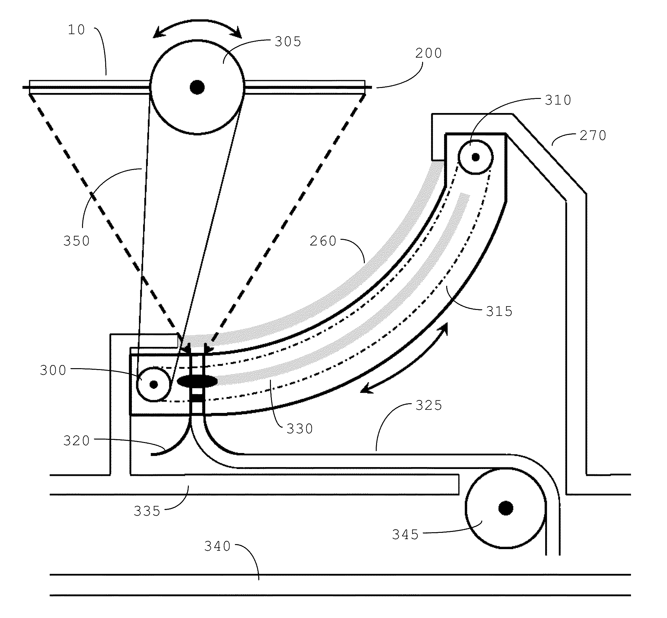
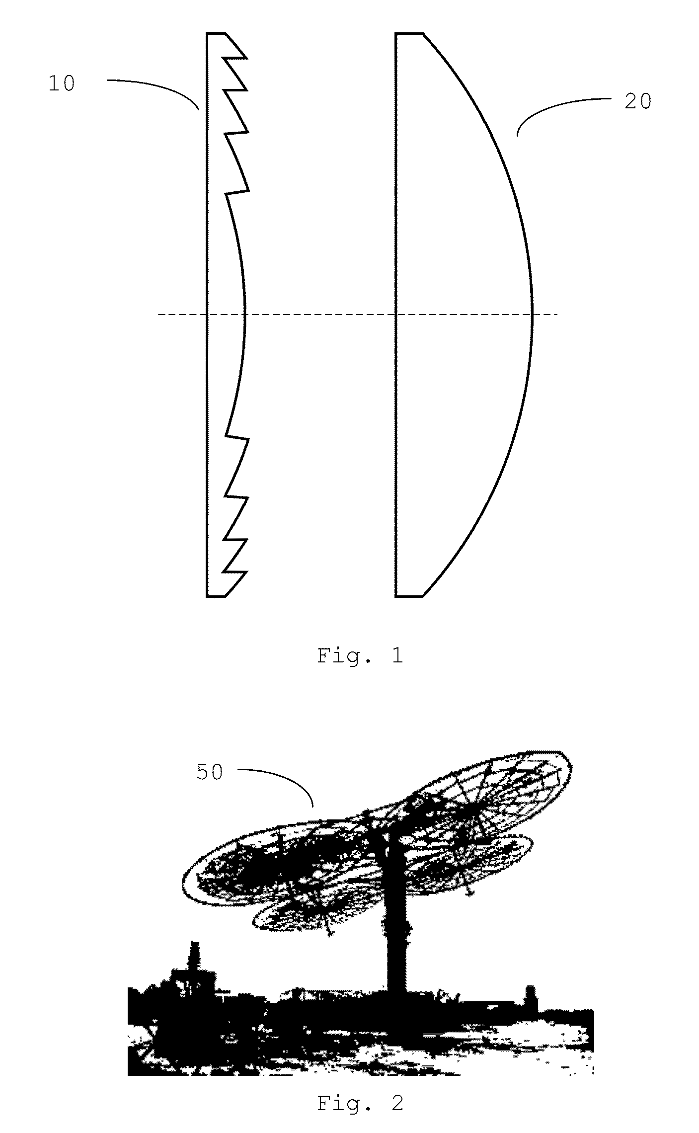
In order to keep a heat engine close to the ground, the point F must be lowered, which can be achieved using optical lenses instead of parabolic reflectors.

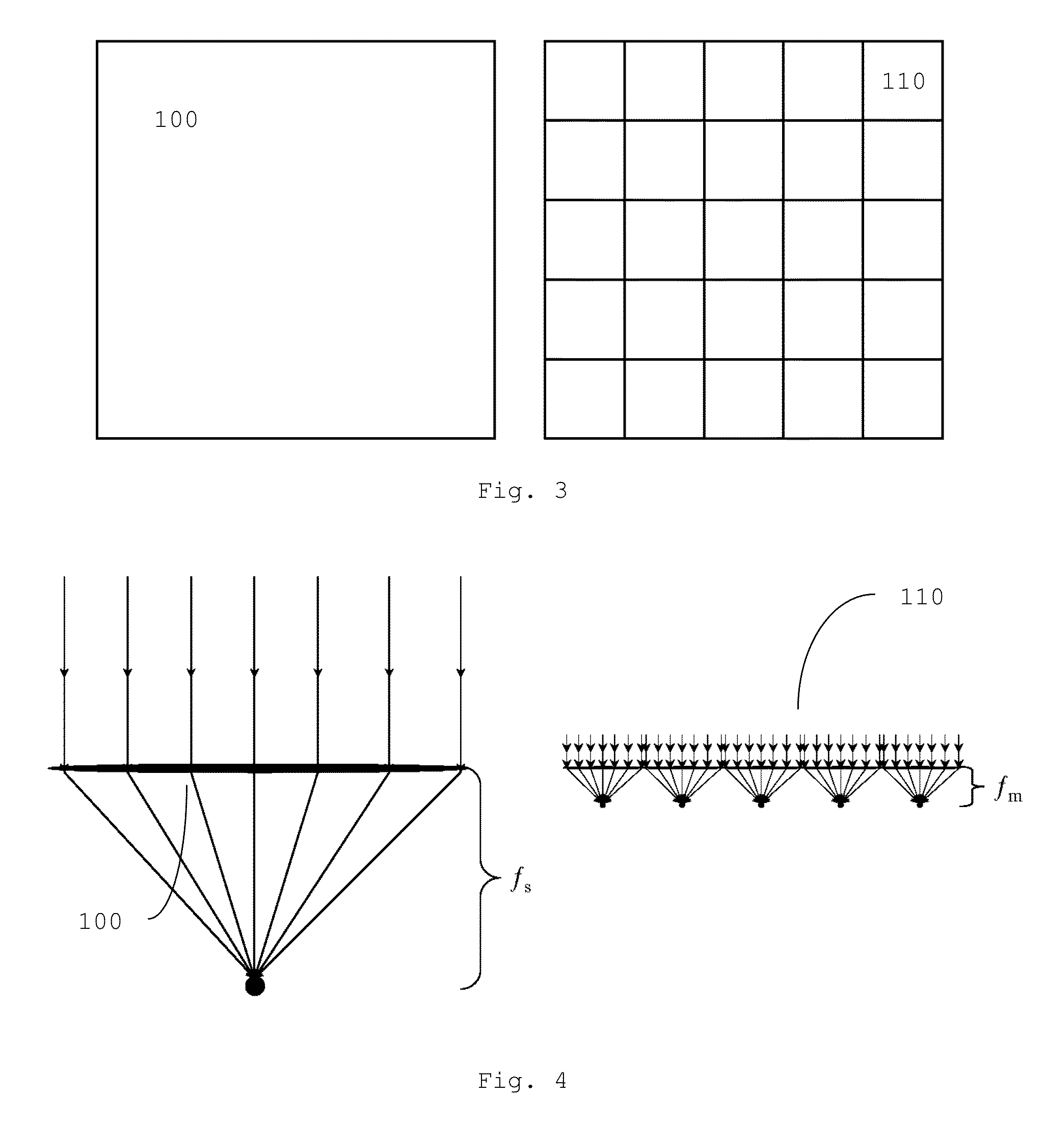
[0055]Designing a Solar Heat Producing System Using Optical Lenses

[0056]Low weight

[0057]Some of the largest Stirling engines...


PUM


Abstract

We present an improved system for solar energy collection and electricity generation, comprising a solar collector apparatus, said apparatus comprising an array of square Fresnel lenses arranged in rows with modular energy absorption devices located below, wherein the array is mounted on arms at a low height above ground, the rows of said array are rotatable horizontally about their lengthwise axis, and the array is mounted on a rotatable baseThe system further comprises transportable insulated storage tanks containing a storage medium, Stirling engines and generators. The solar collection apparatus heats the storage medium, the storage medium supplies the Stirling engines with heat, and each engine is coupled to a generator.In a preferred embodiment, the system additionally comprises embedded controllers using real-time algorithms providing smart on-the-fly management of the system.

Description

CROSS-REFERENCE TO RELATED APPLICATIONS[0001]This application claims U.S. Provisional Application, Ser. No. 61 / 619,041, filed on Apr. 2, 2012.FIELD OF THE INVENTION[0002]The present invention relates to the production of electrical energy from solar thermal energy. In particular, it relates to the collection and storage of solar thermal energy, and the subsequent production of electrical energy therefrom.BACKGROUND OF THE INVENTION[0003]Many systems related to thermally converting solar energy to more useful types of energy have been proposed. For example, International Patent Publication WO 81 / 03220 discloses such a complete system particularly directed to home use, including a Stirling engine coupled to a generator for electricity production. That system has, however, considerable disadvantages, i.a. the use of hot air and rocks as a heat conducting and storage medium, which is somewhat impractical and quite inefficient, as well as the use of a somewhat complex and inefficient sys...

Claims


Application Information

Patent Timeline
Patent Type & Authority Patents(United States)
IPC IPC(8): F03G6/06F24J2/34F24J2/38F24J2/06F24J2/54F24J2/07F24J2/08F24J2/46F28D20/00F24J2/00F24S20/20F24S23/00F24S23/30F24S50/20
CPCF03G6/068F24J2/067F24J2/07F24J2/085F24J2/34F24J2/38F24J2/542F24J2/461F24J2002/0084F24J2002/075F28D20/0056F28D2020/0047Y02E10/41Y02E10/43Y02E10/46Y02E10/47F24S20/20F24S23/12F24S23/31F24S30/452F24S40/20F24S60/00F24S2020/16F24S2020/23F24S50/20Y02E10/40
Inventor LOGOTHETIS, GEORGIOS
Owner LOGOTHETIS GEORGIOS
Why Eureka
Try Eureka