
Apparatus and method for modifying pressure-flow characteristics of a pump

a technology of hydrodynamic pump and characteristic modification, which is applied in the field of ventricular assist device and a method for modifying the characteristics of the hydrodynamic pump, can solve the problems of low flow rate, achieve the effect of less effect on the flow rate of the pump, improve the sensitivity of the pump, and reduce the flow ra

Active Publication Date: 2015-07-28
TC1 LLC
View PDF141 Cites 23 Cited by
  • Summary
  • Abstract
  • Description
  • Claims
  • Application Information

AI Technical Summary

Benefits of technology

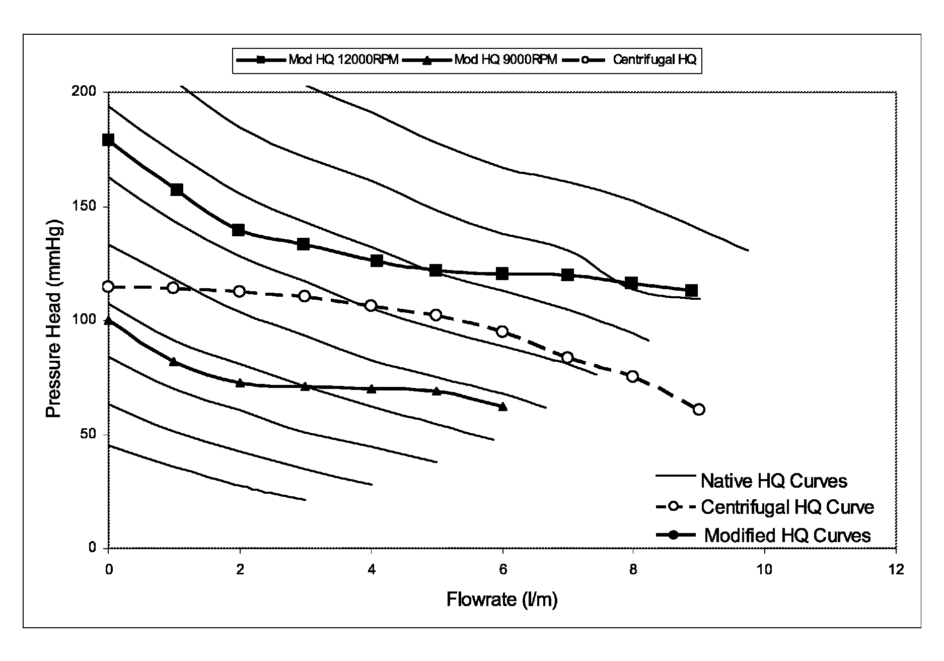
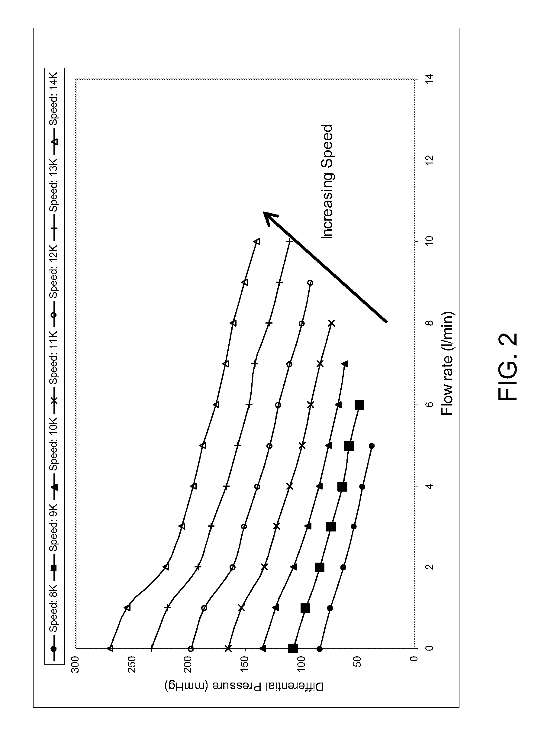
[0012]The H-Q relationship of a pump of a ventricular assist device directly influences how the ventricular assist device responds to changes in physiological conditions, such as changes in physiologic pressures. Clinically it has been suggested that some aspects of the H-Q relationship of a centrifugal flow pump is advantageous due to the increased sensitivity of the pump's flow rate to the pump's differential pressure. To address this difference of the axial flow pump while maintaining its advantages, the inventors of the present application have invented a simple, inexpensive method for modifying the H-Q characteristics of a continuous flow pump to simulate different H-Q characteristics such as more desirable H-Q characteristics. As a result, a ventricular assist device having an axial flow pump that is modified according to the present invention has not only the small size and high flow rate associated with a conventional axial flow pump but also the desirable H-Q characteristics of a centrifugal flow pump. In general, this method can be used to modify any pump to achieve any desired H-Q characteristics.

Problems solved by technology

This implies that, as the pressure differential of the pump increases, it is more difficult for the pump to generate fluid flow, resulting in a lower flow rate.

Method used


Image

  • Apparatus and method for modifying pressure-flow characteristics of a pump
  • Apparatus and method for modifying pressure-flow characteristics of a pump
  • Apparatus and method for modifying pressure-flow characteristics of a pump

Examples


Embodiment Construction

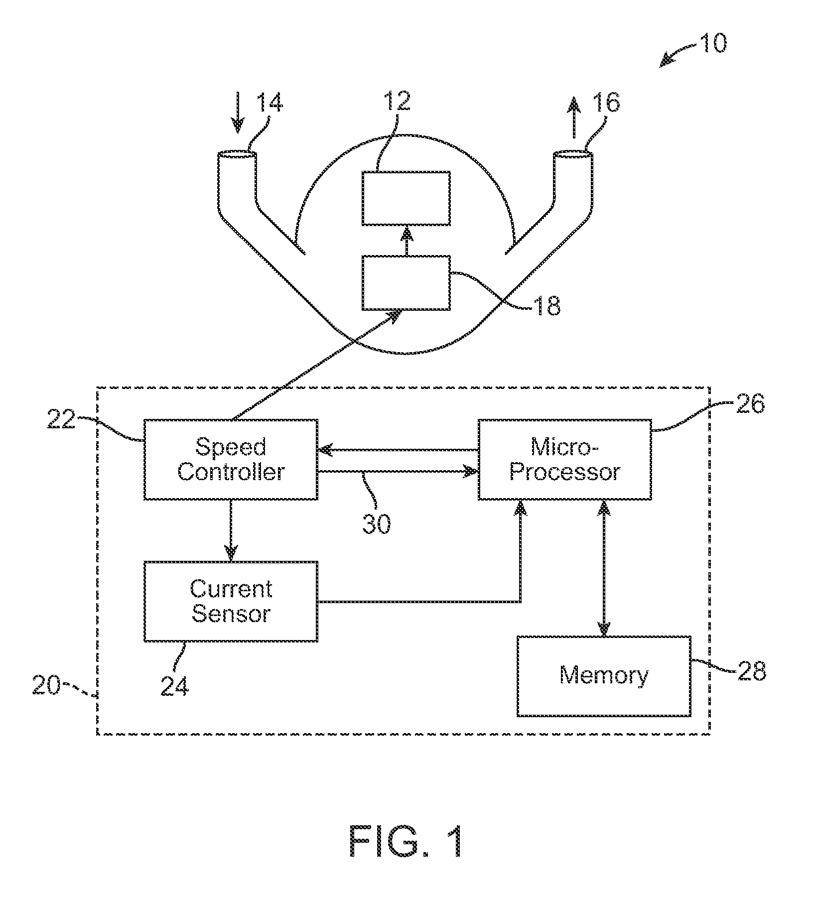
[0057]FIG. 1 shows a schematic diagram of a ventricular assist device 10 according to one embodiment of the present invention. The device 10 includes an implantable blood pump (e.g., a continuous flow pump) 12 in fluid communication with a patient's circulatory system. The blood pump 12 has an inlet 14 and an outlet 16. The inlet 14 may connect to a conduit (not shown) that may in turn connect to a patient's circulatory system, such as at the left ventricle of the patient's heart. The outlet 16 may connect to another conduit (not shown) that may in turn connect to the patient's circulatory system downstream of the first conduit, such as in the aorta. The continuous flow pump 12 can be implanted in the patient's abdomen, chest cavity, or in another location proximate to the heart. Since an implantable blood pump (e.g., an axial blood pump) is well known, the blood pump 12 will not be described in further detail. For exemplary purpose, the blood pump 12 is described herein as a contin...


PUM


Abstract

A method for modifying a pump of a ventricular assist device includes the step of modifying pressure-flow characteristics of a pump of a ventricular assist device to simulate different pressure-flow characteristics or to make the flow rate of the pump more responsive to changes in the pressure differential of the pump. The step of modifying the pressure-flow characteristics of the pump may includes one or both of the steps of (1) estimating a flow rate of the pump from the speed of an electric motor of the ventricular assist device and from the current or power consumption of the electric motor, wherein the electric motor drives the pump, and (2) adjusting the speed of the electric motor as a function of the estimated flow rate of the pump and a set speed of the electric motor to simulate the different pressure-flow characteristics or to make the flow rate of the pump more responsive to changes in the pressure differential of the pump.

Description

CROSS-REFERENCE TO RELATED APPLICATION[0001]This application claims the benefit of U.S. Provisional Application No. 61 / 357,440, filed Jun. 22, 2010, which is incorporated herein by reference.FIELD OF THE INVENTION[0002]The present invention relates to a ventricular assist device and a method for modifying the characteristics of the hydrodynamic pump of a ventricular assist device, in particular to a method for modifying the pressure-flow characteristics of the hydrodynamic pump of a ventricular assist device. The present invention further relates to a computer readable storage medium wherein such an invention is stored.BACKGROUND OF THE INVENTION[0003]The human heart is a pump—a complex and critical pump. The heart can become damaged or dysfunctional over time. When wear and damage to the heart become sufficiently serious, the heart fails to pump and circulate blood normally, resulting in a condition known as heart failure. Around the world millions of people suffer from heart failu...

Claims


Application Information

Patent Timeline
Patent Type & Authority Patents(United States)
IPC IPC(8): A61M1/10A61M1/12
CPCA61M1/1086A61M1/122A61M1/10A61M1/101A61M1/1001A61M2205/3334A61M60/148A61M60/546A61M60/237A61M60/178A61M60/523
Inventor REICHENBACH, STEPHEN H.LAW, YU FAI
Owner TC1 LLC
Learn More