
Slide part

a technology of sliding parts and sliding joints, applied in the direction of liquid fuel engine components, rotary piston liquid engines, trunk pistons, etc., can solve the problems of amorphous carbon coating mechanical wear, amorphous carbon coatings can wear away significantly, and amorphous carbon coatings can be mechanically worn, so as to achieve superior high wear resistance and low frictional properties.

Active Publication Date: 2015-07-28
HITACHI METALS LTD
View PDF18 Cites 2 Cited by
  • Summary
  • Abstract
  • Description
  • Claims
  • Application Information

AI Technical Summary

Benefits of technology

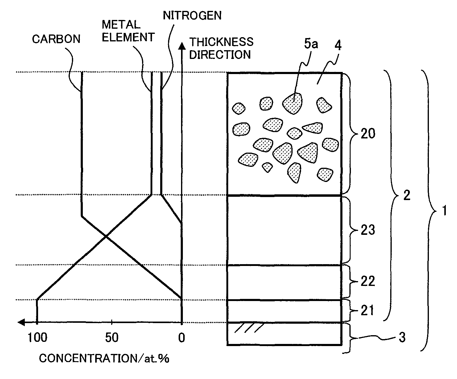
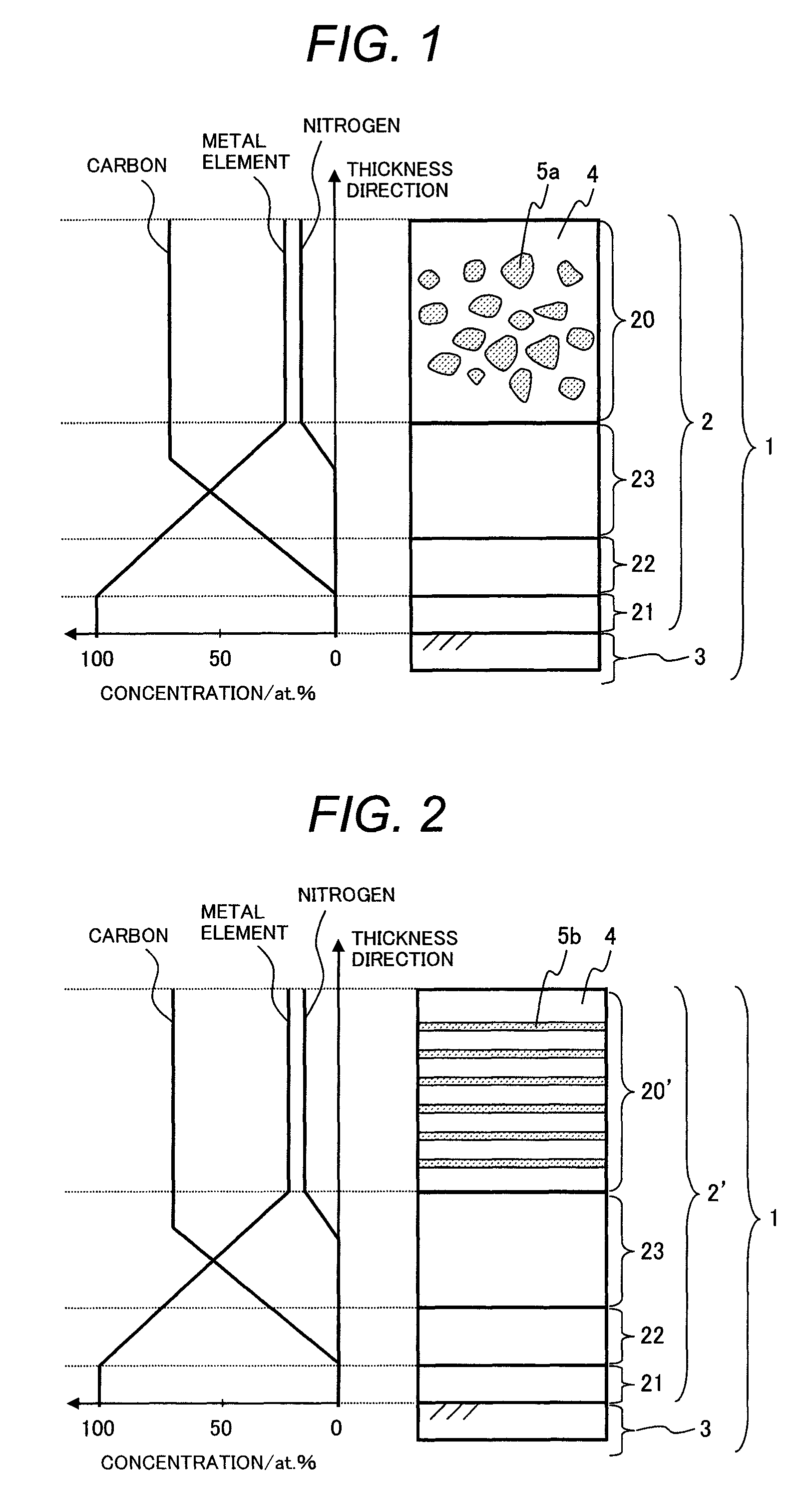
[0060]A hard protective layer according to the present invention comprises mainly amorphous carbon, which intrinsically has a high hardness and a high toughness, and is a complex with a microstructure that can inhibit weakening of the amorphous carbon. As a result, it exhibits superior durability against the above mentioned chemical mechanical wear. At the same time, the hard protective layer of the present invention exhibits superior low frictional properties in a lubricant containing additives including oil additives, extreme-pressure additives, and friction reducers, as it contains a metal element in a moderate amount, which promotes interaction with those additives.

Problems solved by technology

According to these Academic Documents, Mo-DTC in a lubricant is thermally decomposed to produce molybdenum disulfide and molybdenum oxides, and molybdenum trioxide, in particular, is deeply involved in wear in amorphous carbon coatings.
Meanwhile, Jia et al. claim that amorphous carbon coatings mechanically wear due to hard and sharp molybdenum trioxide.
Unfortunately, however, as reported in the above Academic Documents 2 and 3 and JP 2008-195903 A, amorphous carbon coatings can wear away significantly in a sliding environment where there is a lubricant containing molybdenum compounds including Mo-DTC (molybdenum dialkyldithiocarbamate) and Mo-DTP (molybdenum dithiophosphate), which are known as friction modifiers.
On the other hand, it is an extremely important challenge to further improve friction properties and wear resistance of slide parts as typified by automobile parts in order to meet the growing needs for environmental protection and energy conservation.
This can be attributed to the fact that the wear mechanism has not been fully understood, among other things.

Method used


Image

  • Slide part
  • Slide part
  • Slide part

Examples


preparation of example 1

[0089]The method for manufacturing a slide part specimen in Example 1 is as follows. A steel substrate, a metal target, and a graphite target were set in a non-equilibrium magnetron sputtering device, and argon gas, hydrocarbon gas, and nitrogen gas were supplied to form a hard protective layer on the surface of the steel substrate by the reactive sputtering method.

[0090]More specifically, first, the first interlayer 21 composed of only metal was formed by supplying argon gas and applying electric power to the metal target. Next, the second interlayer 22 composed of metal and the metal carbide and the third interlayer 23 composed of the metal carbide and amorphous carbon were formed by supplying argon gas and hydrocarbon gas while continually varying the amount of electric power applied to the metal target and the graphite target. Finally, the hard protective layer was formed by supplying argon gas, hydrocarbon gas, and nitrogen gas and applying electric power to the metal target an...

examples 17 to 24

Preparation and Evaluation of Examples 17 to 24 and Comparative Examples 19 to 22

[0123]The specimens in Examples 17 to 24 and Comparative Examples 19 to 22 were prepared by forming a hard coating on the surface of an actual automobile part by a manufacturing method similar to the above. In Examples 17 to 20 and Comparative Examples 19 and 20, a hard coating was formed on the top surface of a valve lifter in a motoring engine simulating a direct-acting valve system. In Examples 21 to 24 and Comparative Examples 21 and 22, a hard coating was formed on the surface of each vane in a vane oil pump. Endurance tests were conducted in an actual equipment using an engine oil containing Mo-DTC (viscosity index: 0 W-20) as a lubricant to evaluate durability. The results are shown in Table 3.

[0124]

TABLE 3ExampleExampleExampleExampleExampleExampleExample17181920212223Manufacturing methodReactiveReactiveReactiveReactiveReactiveReactiveReactivesputteringsputteringsputteringsputteringsputteringsput...


PUM

PropertyMeasurementUnit
particle sizeaaaaaaaaaa
vol. %aaaaaaaaaa
thicknessaaaaaaaaaa

Abstract

There is provided a slide part used in an environment where there is a lubricant containing a molybdenum compound including a hard protective layer formed on an outermost surface of a substrate of the slide part; in which: the hard protective layer includes mainly carbon, nitrogen, and a metal element; the hard protective layer is composed of a complex of an amorphous carbon body containing nitrogen and a compound crystal of the metal element; the compound crystal is composed of at least one of a metal carbide, a metal nitride, and a metal carbonitride; and a surface hardness of the hard protective layer is 1800 or larger in Vickers hardness.

Description

CLAIM OF PRIORITY[0001]The present application claims priority from Japanese patent applications: serial no. 2009-199201 filed on Aug. 31, 2009; and serial no. 2010-123648 filed on May 31, 2010, the contents of which are hereby incorporated by reference into this application.BACKGROUND OF THE INVENTION[0002]1. Field of the Invention[0003]The present invention relates to a slide part used in a lubricated environment, and more particularly, to a slide part with an amorphous carbon coating formed on its sliding surface.[0004]2. Description of the Related Art[0005]Slide parts with amorphous carbon coatings formed on their sliding surfaces have been under intense research and development in order primarily to lower friction at sliding points particularly of automobile parts. Thin film materials referred to as DLC (diamond-like carbon), i-C (i-carbon), hard carbon, etc. are commonly used for amorphous carbon coatings.[0006]Since amorphous carbon coatings are amorphous structures with no g...

Claims


Application Information

Patent Timeline
Patent Type & Authority Patents(United States)
IPC IPC(8): B32B9/00C23C14/06C23C14/00C23C28/00
CPCC23C14/0605C23C14/0036C23C14/0641C23C28/32C23C28/343C23C28/36Y10T74/19Y10T428/12549Y10T428/24975Y10T428/25F16C33/043F16C2202/04F16C2206/04
Inventor SUGIMOTO, ITTOOKAMOTO, KAZUTAKAHONDA, FUMIAKIINOUE, KENICHI
Owner HITACHI METALS LTD
Learn More