Microfluid testing system with a multiple-channel disc and utility thereof

a microfluidic disc and testing system technology, applied in the field of fluid testing system, can solve the problems of extremely few specimens and reagents, fast testing, etc., and achieve the effects of reducing the number of specimens, and reducing the number of test results

Active Publication Date: 2015-07-28
CHUNG YUAN CHRISTIAN UNIVERSITY
View PDF2 Cites 12 Cited by
  • Summary
  • Abstract
  • Description
  • Claims
  • Application Information

AI Technical Summary

Benefits of technology

[0011]The disc module production of the present invention adopts traditional low-cost technology, using at least one transparent substrate which is produced and prepared by carving or injection molding. Through the calibration and calculation of the built-in software in the multichannel microfluidic disc testing system, the instrument will directly show the type and the density of the factors waiting to be examined. In addition, the multichannel microfluidic disc testing system uses the disposable disc module, so it won't be easily damaged by the pollution of the specimens and reagents. The reliability will be greatly enhanced and the longevity of this system will also be prolonged substantially. The multichannel microfluidic disc testing system can be installed in medical facilities and laboratories which have the need to test few or important specimens. The multichannel microfluidic disc testing system is composed of the disposable disc module and the multichannel microfluidic disc image recognition system. Due to its simple production of the disc module, convenient testing process, low cost, lower environment limit, the present invention and its skill advantages are more advantageous than other common microplate methods. At the same time, it requires extremely few specimens and reagents, and the testing is fast. Moreover, compared with the traditional manual matching and analysis, the operators of the present invention can use it by themselves and directly read the statistics to make judgments without being equipped with professional knowledge of medicine or chemistry.
[0012]Another objective of the present invention is to provide a kind of disposable disc, which is composed of at least one transparent substrate and at least one testing mechanism. The testing mechanism includes at least one feeding aperture, at least one vent chamber, at least one feeding chamber, at least reaction chamber, at least one reaction testing zone, at least one waste chamber, at least one microfluidic channel and at least one capillary valve. They are manufactured and prepared by carving or injection molding, and this process can be operated in the common environment. The structure of the testing mechanism can be designed according to the coagulation formation process of the factors waiting to be examined. The disc module of the present invention is disposable so the production is inexpensive and is easy to operate.
[0013]The current microplate methods and traditional manual operations cost a bit higher and consume more specimens and reagents. To overcome the drawbacks of the past biofluidic testings, the present invention has the following advantages: low cost, convenient operation, smaller quantity of specimens and reagents, and shorter reaction time. It is to replace the traditional multichannel microfluidic disc testing system. The present invention can lower the quantity of specimens, reagents and shorten reaction time, so the tests of the existence and density of the factors waiting to be examined in the specimens can be run fast with a low quantity of specimens and reagents, which is a very practical and convenient testing device for medical facilities and laboratories.
[0016]The abovementioned microfluidic channel has a specific bending angle which can control the discharging rate of the microfluids through the centrifugal rotational speed, and prevent reverse flow of the microfluids. Wherein, the smaller the bending angle is, the bigger the resistance of the reverse flow is. The abovementioned reaction chamber further includes at least one waste chamber to receive the waste fluid from the reaction chamber. The abovementioned microfluidic channel connects the reaction chamber with the waste chamber, and forms a level inclination at the connection. Wherein, the microfluidic channel exit near the waste chamber should be higher than the microfluidic channel entrance near the reaction chamber to prevent reverse flow of the microfluids. There is a specific joint angle at the connection between the abovementioned microfluidic channel and the feeding chamber, which controls discharging rate of the microfluids through the centrifugal rotational speed, and prevents reverse flow of the microfluids. There is a capillary valve at the connection between the abovementioned microfluidic channel and the feeding chamber, which controls the discharging rate of the microfluids through the centrifugal rotational speed, and prevents reverse flow of the microfluids. The abovementioned capillary valve forms an interlocked combination of at least one convex channel and at least one cavernous channel on the microfluidic channel to form a serrated appearance. The diameter of the abovementioned convex channel is bigger than that of the cavernous channel, and the diameter of the convex channel is also bigger than that of the microfluidic channel.

Problems solved by technology

At the same time, it requires extremely few specimens and reagents, and the testing is fast.

Method used


Image

  • Microfluid testing system with a multiple-channel disc and utility thereof
  • Microfluid testing system with a multiple-channel disc and utility thereof
  • Microfluid testing system with a multiple-channel disc and utility thereof

Examples


first embodiment

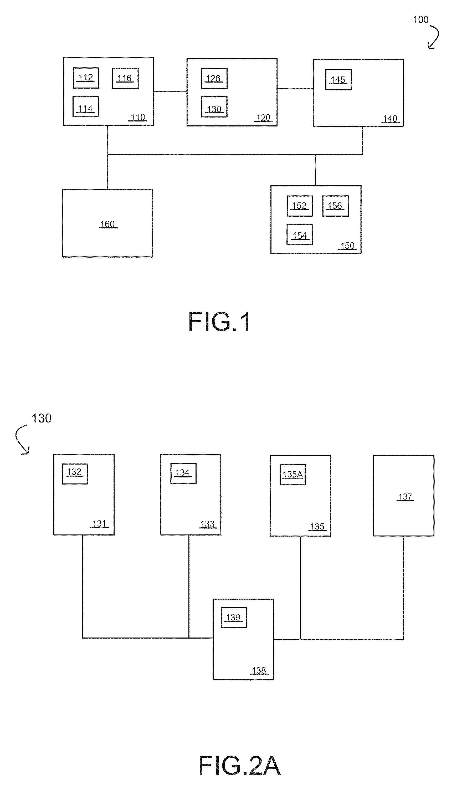
[0033]Referring to FIG. 1, according to the present invention, the present invention provides a multichannel microfluidic disc testing system 100, which includes a dosing module 110, a disc module 120, an image module 140, an analysis and control module 150 and an energy module 160. The abovementioned dosing module 110 further includes at least one transporting device 112, at least one dosing device 114, at least one revolving device 116. Wherein, the dosing module 110 is located in a specific place on the revolving direction of the disc module 120. The transporting device 112 moves the dosing device 114 to provide the reagents to the disc module 120. The revolving device 116 provides kinetic energy to the disc module 120 to proceed the centrifugal motion to enable the reagents to react in the disc module 120. The abovementioned disc module 120 further includes at least one fixed mechanism 126 and one testing mechanism 130. Wherein, the disc module 120 is fixed on the revolving 116 ...

second embodiment

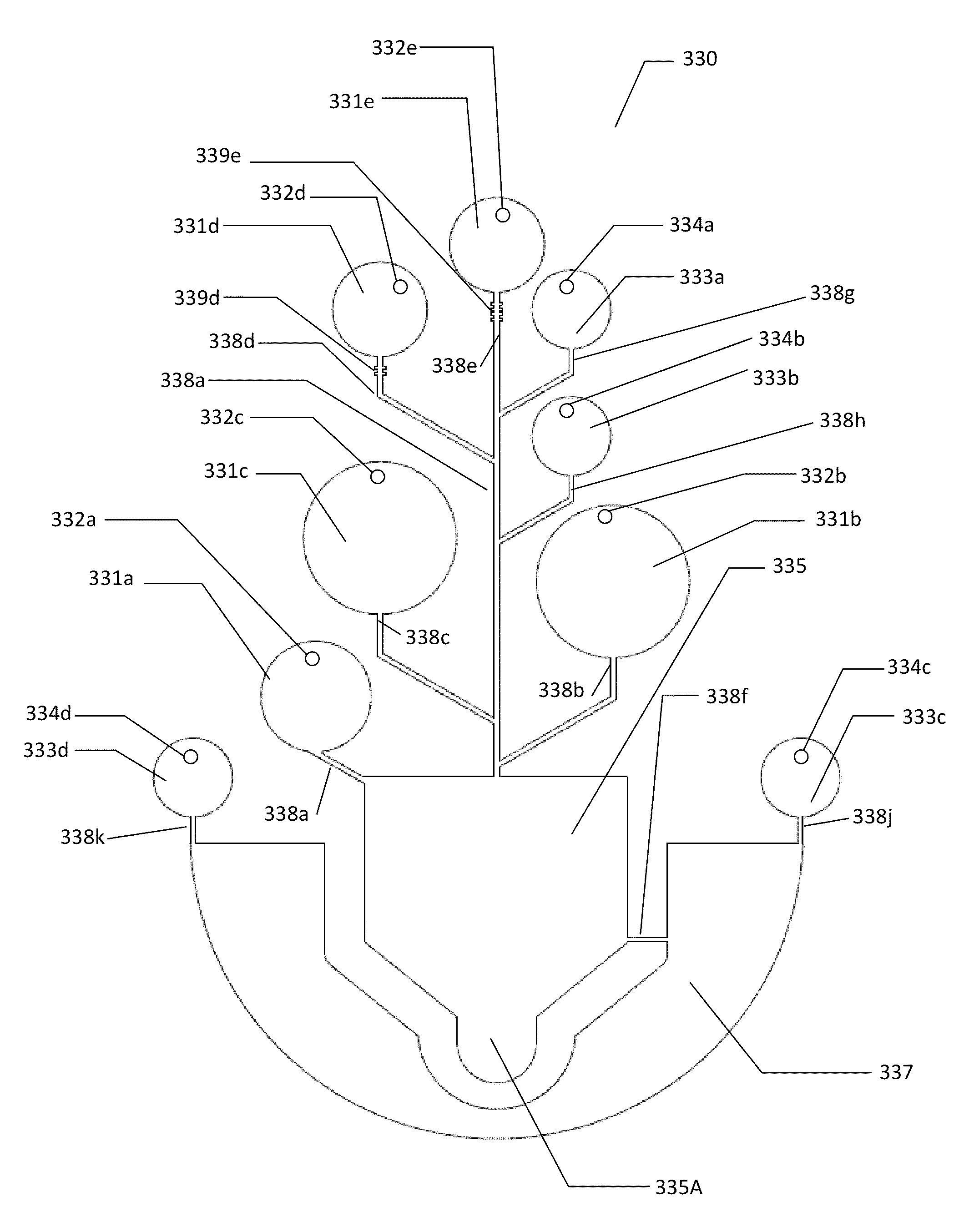
[0037]Referring to FIGS. 4A and 4B, according to the present invention, the present invention provides a multichannel microfluidic disc testing device 300, which includes one supporting mechanism 310, multiple supporting devices 311, at least one moving component 312, at least one dosing component 314, at least one revolving component 316, one disc 320, one image sensing component 345, one analysis component 352, one control component 354, one display component 356 and one power source component 360. The multiple supporting devices 311 are used to support, clip or hold each component, and can directly form in a specific area on the supporting mechanism 310 or can be made separately. The abovementioned moving component 312 is used to transport or move the dosing component 314 so that it can add reagents to the disc 320. The dosing component 314 is used to control storing, loading, transporting and injecting various kinds of microfluid medicaments / reagents to the disc 320 so that they...


PUM

PropertyMeasurementUnit
diameteraaaaaaaaaa
diameteraaaaaaaaaa
diameteraaaaaaaaaa

Abstract

The present invention discloses a system for testing microfluid which is made with a disposable disc. The high sensitivity, high sensing accuracy, and quick response microfluidic disc is demonstrated in the present invention. It is note that easy to test microfluid without traditional detecting method, and then reduce energy and simplify procedure. Furthermore, to additive the microfluidic disc is useful to enhance blood typing, and hence raising the sensitivity by the video recognition of blood agglutination.

Description

BACKGROUND OF THE INVENTION[0001]1. Field of the Invention[0002]This invention generally relates to the field of fluid testing system, and more particularly, to a multichannel microfluidic disc testing system and utility thereof.[0003]2. Description of the Prior Art[0004]Nowadays, the examination of specific biofluid is often needed as a basis for diagnosis in biomedical field. Currently, one of the known blood identification methods is microplate method, which has been used extensively in various medical examinations.[0005]This method requires manual operation on a 96-well plate; therefore, it consumes a lot of time, manpower, specimens and reagents. In all kinds of medical products and researches, such as blood test, body fluid test and medical reagent test, etc, biofluid is often used to run the test, for example, blood typing test, disease diagnostic test and the screening of medicament in development. Generally speaking, these specimens and reagents tend to be few, expensive an...

Claims


Application Information

Patent Timeline
Patent Type & Authority Patents(United States)
IPC IPC(8): G01N33/00B01L3/00G01N33/80
CPCG01N33/80B01L3/502746B01L2200/0621B01L2300/0803B01L2300/0867B01L2400/0409B01L2400/0688B01L2400/084B01L3/502769G01N33/50B01L2300/0806
Inventor HSIUE, GING-HOCHEN, SHIA-CHUNGLI, WEN-TYNGCHANG, YAW-JENCHANG, YUNGFAN, YI-HUAHSIEH, MING-FALIAO, WEI-LIANGCHEN, CHING-ENHUANG, CHING-WEILIANG, YING-MING
Owner CHUNG YUAN CHRISTIAN UNIVERSITY
Why Eureka
Try Eureka