
Electrical energy store and method for closed-loop control of such energy store

a technology of electric energy store and closed-loop control, which is applied in the direction of secondary cell charging/discharging, ac-dc network circuit arrangement, ac network load balancing, etc., can solve the problem of principally inability to influence the availability of such energy store, reducing the maximum power capacity of the storage system, and unable to achieve optimum efficiency

Inactive Publication Date: 2015-07-28
ENEROX GMBH
View PDF5 Cites 5 Cited by
  • Summary
  • Abstract
  • Description
  • Claims
  • Application Information

AI Technical Summary

Benefits of technology

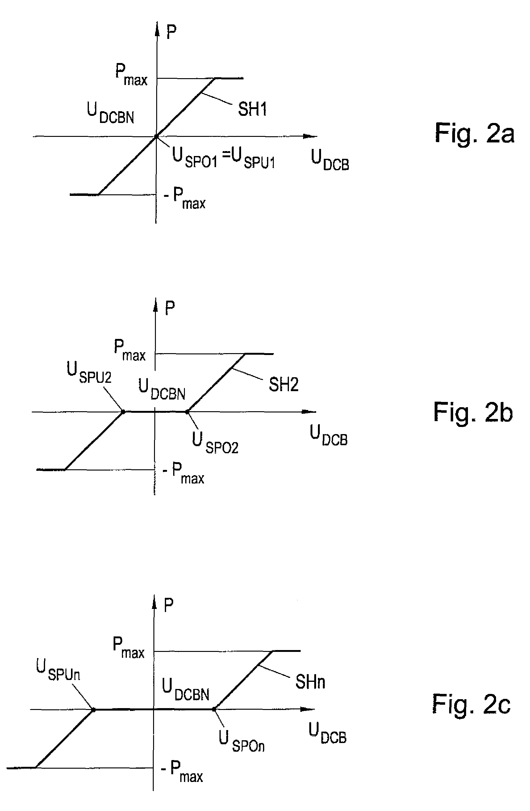
The invention relates to an energy store that uses a multiplicity of cell stacks equipped with DC / DC converters, which can achieve a finely controllable power range in a simple manner. The energy store is connected to a DC bus through a DC / DC converter, which allows for simple control of power consumption and output. A central control unit can easily change the settings or parameters of the converter through a data bus. The technical effects of the invention are a simplified and fine-controlled power range for an energy store and a simplified and flexible control of power consumption and output for an installation using the energy store.

Problems solved by technology

A main problem of alternative energy such as, e.g., solar energy or wind power, is the availability thereof which principally cannot be influenced.
If a storage system is built from a few cell stacks or modules, e.g., in the 100 kW range, this adaptation can take place only in very large discrete steps so that the optimum efficiency increase cannot be achieved.
Moreover, damage to a unit results in a considerably reduced maximum power capacity of the storage system.
When using large batteries, there is the additional disadvantage that much effort is necessary for a stable closed-loop control because the systems are controlled in master-slave operation.
As soon as the number becomes high, the individual modules often can only be controlled in blocks so that often no optimal operation is ensured.
The disadvantage here is that closed-loop control of such a system, e.g., through a central control and a bus system is complex and interference-prone.
Here too, there is the problem of high granularity of the power range, or of the need of a complicated closed-loop control.

Method used


Image

  • Electrical energy store and method for closed-loop control of such energy store
  • Electrical energy store and method for closed-loop control of such energy store
  • Electrical energy store and method for closed-loop control of such energy store

Examples


Embodiment Construction

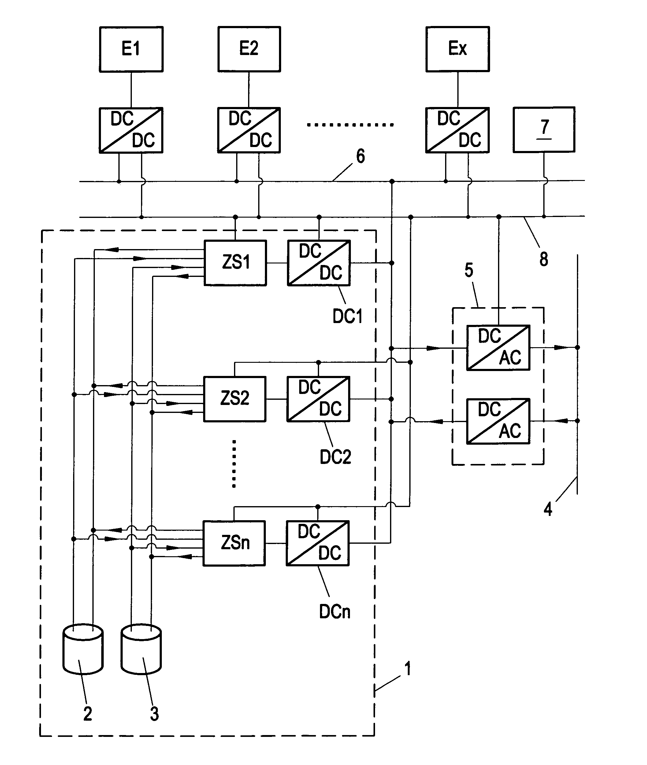
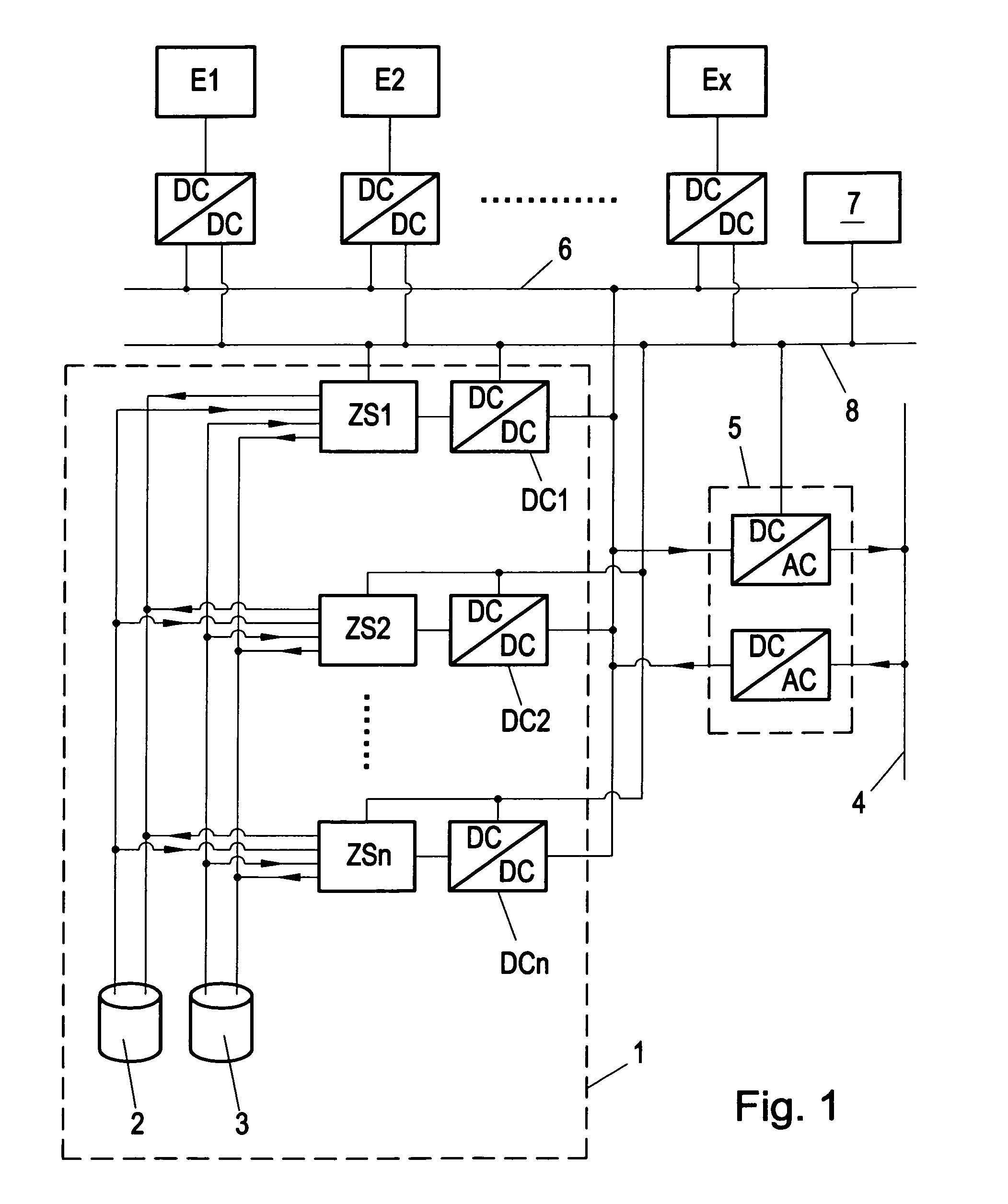
[0022]FIG. 1 shows an installation for generating alternative energy with energy generating units E1, e.g., a wind power plant, E2, e.g., a photovoltaic installation and Ex, e.g., a generator, which each supply via a DC / DC converter into a DC bus 6. For storing excessive energy or for compensating an energy deficit, an energy store, here, e.g., a redox flow battery 1, is provided which is also connected to the DC bus 6. An electrical supply grid 4 to which a non-illustrated load is connected is supplied via a DC / AC converter 5. It can also be provided, as indicated in FIG. 1, that the supply grid 4 supplies back via the DC / AC converter 5, e.g., so as to charge the energy store which is in this case the redox flow battery 1. The DC / AC converter 5 operates here as a command variable in the supply grid 4 or can be operated parallel to an existing supply grid. Further units such as e.g., a PV inverter can be connected via a DC / AC converter to the supply grid 4, or an emergency generator...


PUM


Abstract

In installations for generating alternative energy it is necessary due to the fluctuating availability of the alternative energy source to provide electrical energy stores which can temporarily store excess energy or can compensate for energy bottlenecks. The present invention relates to such an electrical energy store having a bidirectional DC / DC converter with a low-voltage side and a high-voltage side which can be connected via the high-voltage side to a DC bus and which has a switching hysteresis with a charging and / or discharge curve, wherein power consumption and / or power output are / is dependent on a voltage on the high-voltage side.

Description

BACKGROUND OF THE INVENTION[0001]1. Field of the Invention[0002]The present invention relates to an electrical energy store having a bidirectional DC / DC converter, to a method for controlling such an energy store, and to the integration of such an energy store in an installation for storing electrical energy.[0003]2. The Prior Art[0004]A main problem of alternative energy such as, e.g., solar energy or wind power, is the availability thereof which principally cannot be influenced. When generating alternative energy it is therefore desirable to temporarily store energy in times of excess energy so as to be able to deliver the energy again in times of high demand and low availability of alternative energy. As storage for electrical energy, energy stores such as, e.g., batteries are well suited. Particularly suitable are redox flow batteries, which are known per se, such as, e.g., vanadium redox flow batteries. Large battery systems usually consist of a multiplicity of small cells conn...

Claims


Application Information

Patent Timeline
IPC IPC(8): H02J4/00H02J3/32H02J7/00
CPCH02J4/00H02J3/32H02J7/0018
Inventor TRIEBEL, CLEMENSBOSCH, ERICH
Owner ENEROX GMBH
Learn More