Home laundry drier

a technology for drying racks and dryers, which is applied in the direction of washing machines, laundry drying equipment, sustainable buildings, etc., can solve the problems of increasing drying time, clogging up of closed circuits, and loss of pressure inside the air recirculating conduits

Active Publication Date: 2015-08-04
ELECTROLUX HOME PROD CORP NV
View PDF16 Cites 24 Cited by
  • Summary
  • Abstract
  • Description
  • Claims
  • Application Information

AI Technical Summary

Benefits of technology

[0013]It is an aim of the present invention to provide a rotary-drum home laundry drier designed to eliminate the aforementioned drawbacks.

Problems solved by technology

Unluckily, despite the fact that there are several removable air-filters located in the air recirculating conduit, during the flowing of the air through the revolving drum, particles of lint / fluff / dust build up inside of the first and second air / refrigerant heat exchanger, causing a gradual clogging up of the closed-circuit which creates loss of pressure inside the air recirculating conduit.
As a result of the loss of pressure inside the recirculating conduit, the rotation speed of the centrifugal fan and the flow rate of the air flow tend to gradually decrease, causing the drawback that the drying time increases and, consequently, the drying process slows down.
Due to the fact that the rotation speed of the centrifugal fan decreases, the electric motor is subjected to slow down and works under stress causing disadvantageous higher electricity power consumption.
In addition, the air temperature inside the heat pump assembly tends to gradually increase, reaching a high value which may both cause damage to the clothing and several heat dissipation problems at the compressing device of the heat-pump device.
In detail, in that event, the heat-pump device needs to operate at full capacity, but the compressing device may not be able to absorb by means of the evaporator a sufficient amount of heat from the airflow so as to maintain the air temperature in the air recirculating conduit under a safety threshold over which the compressing device is automatically turned off by an auxiliary safety dryer device.
Finally, it should be understood that when the compressing device operates in the full capacity state, it becomes quite noisy and unfortunately its operating life decreases.

Method used


Image

  • Home laundry drier
  • Home laundry drier
  • Home laundry drier

Examples


Embodiment Construction

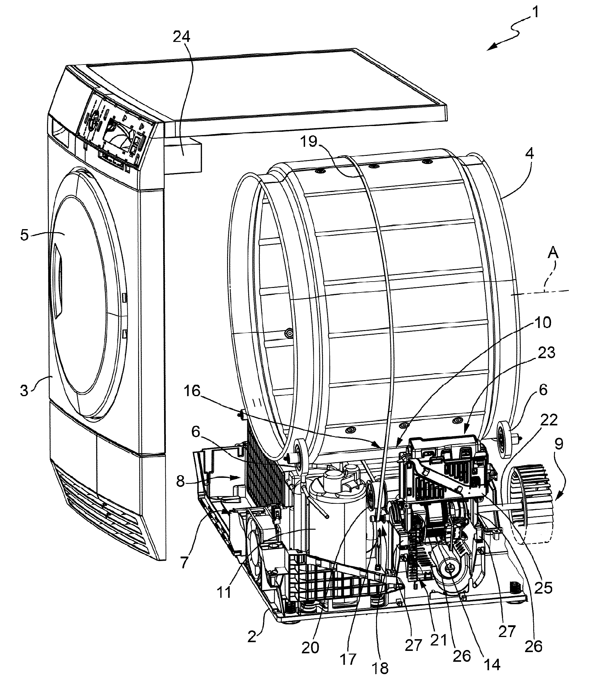
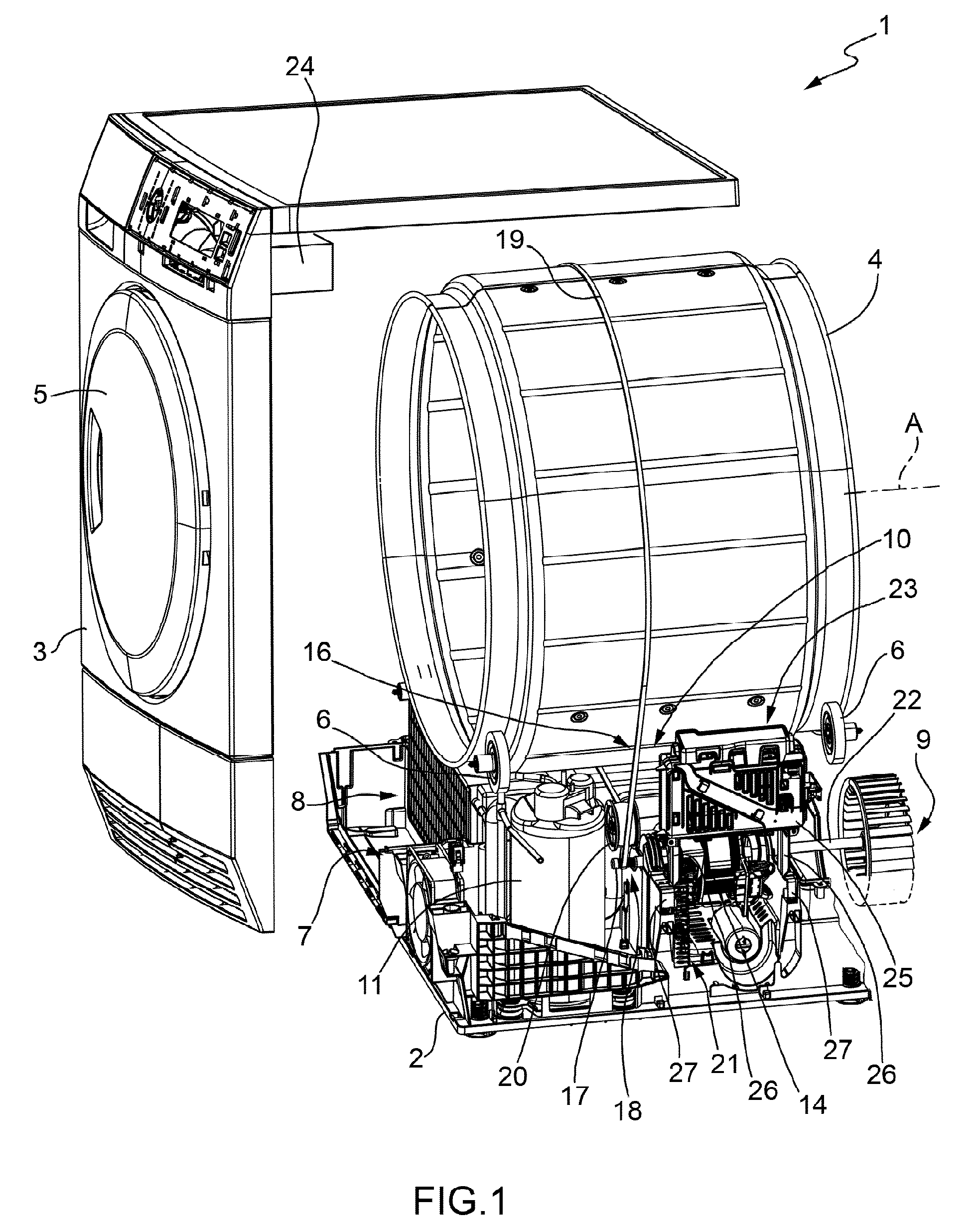
[0035]With reference to FIG. 1, number 1 indicates as a whole a home laundry drier comprising a base 2 resting on the floor; a casing 3 designed to be fixed stably, but in easily removable manner, to the base 2, by fixing means; a cylindrical revolving laundry drum 4 for housing the laundry to be dried, and which is fixed in axially rotating manner inside casing 3 above the base 2, directly facing a laundry loading and unloading opening (not shown) formed in the front face of casing 3; and a door 5 hinged to the front face of casing 3 to rotate to and from a rest position closing opening in the front face to seal revolving laundry drum 4.

[0036]Preferably, the revolving laundry drum 4 rests horizontally inside casing 3 on a number of horizontal supporting rollers 6 which are fitted to casing 3 to let revolving drum 3 freely rotate about its longitudinal axis A.

[0037]Casing 3, revolving laundry drum 4, door 5 and supporting rollers 6 are commonly known parts in the industry, and there...


PUM


Abstract

A home laundry drier (1) includes a laundry drum (4) which is located inside a casing (3) to rotate about an longitudinal axis (A), and a closed circuit hot-air generator (7) provided with: an air recirculating conduit (8) connected to laundry drum (4); a centrifugal fan (9) and heat-pump means (10). The heat pump means (10) includes first (12) and second air/refrigerant heat exchangers (13) located in the air recirculating conduit (8) to cool the airflow coming out from the laundry drum, and respectively, to heat the airflow returning back into laundry drum (4). The home laundry drier (1) further includes an electric motor (14) designed to simultaneously rotate both centrifugal fan (9) and the laundry drum (4) through transmission system means (16); and inverter means (23) controlling the electric motor (14) and configured to receive a predetermined speed which is associated to a nominal airflow rate within the air recirculating conduit (8) and to a nominal drum speed. The electric motor (14) is controlled so that the output motor speed is maintained substantially equal to a predetermined speed, independently of decreasing of the airflow rate caused by clogging-up of particles within the first (12) and/or second air/refrigerant heat exchangers (13) of the heat-pump means (10).

Description

BACKGROUND[0001]The present invention relates to a home laundry drier.[0002]More specifically, the present invention relates to a rotary-drum home laundry drier comprising: a substantially parallelepiped-shaped outer box casing; a cylindrical bell-shaped drum for housing the laundry to be dried, and which is located in axially rotating manner inside the casing to rotate about its horizontally oriented longitudinal axis, directly facing a laundry loading and unloading opening formed in the front face of the casing; a door hinged to the front face of the casing to rotate to and from a rest position closing the opening in the front face of the casing to seal the casing and the bell-shaped drum.[0003]Further, a rotary-drum laundry drier of the above type comprises a closed-circuit, a hot-air generator designed to circulate inside the revolving drum a stream of hot air with a low moisture content, and which flows through the revolving drum and over the laundry inside the drum to rapidly ...

Claims


Application Information

Patent Timeline
Patent Type & Authority Patents(United States)
IPC IPC(8): D06F58/20F26B21/08D06F58/08D06F58/28
CPCD06F58/206D06F58/28F26B21/086D06F58/08D06F58/20Y02B40/72D06F2058/2858D06F2058/2864D06F2058/2877D06F58/50D06F2101/20D06F2103/34D06F2103/36D06F2103/44D06F2103/50D06F2105/24D06F2105/46D06F2105/48Y02B40/00
Inventor LORENC, MARCINROS, PAOLO
Owner ELECTROLUX HOME PROD CORP NV
Why Eureka
Try Eureka