Laser-sustained plasma light source

a plasma light source and laser-sustained technology, applied in plasma techniques, discharge tube main electrodes, hollow cathodes of discharge tubes, etc., can solve problems such as significant instability of plasmas, and achieve the effects of reducing the noise in the collected radiation, maximizing radiation, and enhancing heat transfer

Active Publication Date: 2015-08-04
KLA CORP
View PDF9 Cites 55 Cited by
  • Summary
  • Abstract
  • Description
  • Claims
  • Application Information

AI Technical Summary

Problems solved by technology

Such plasmas show significant instability when operating in high pressure gases, such as xenon.

Method used


Image

  • Laser-sustained plasma light source
  • Laser-sustained plasma light source

Examples


Embodiment Construction

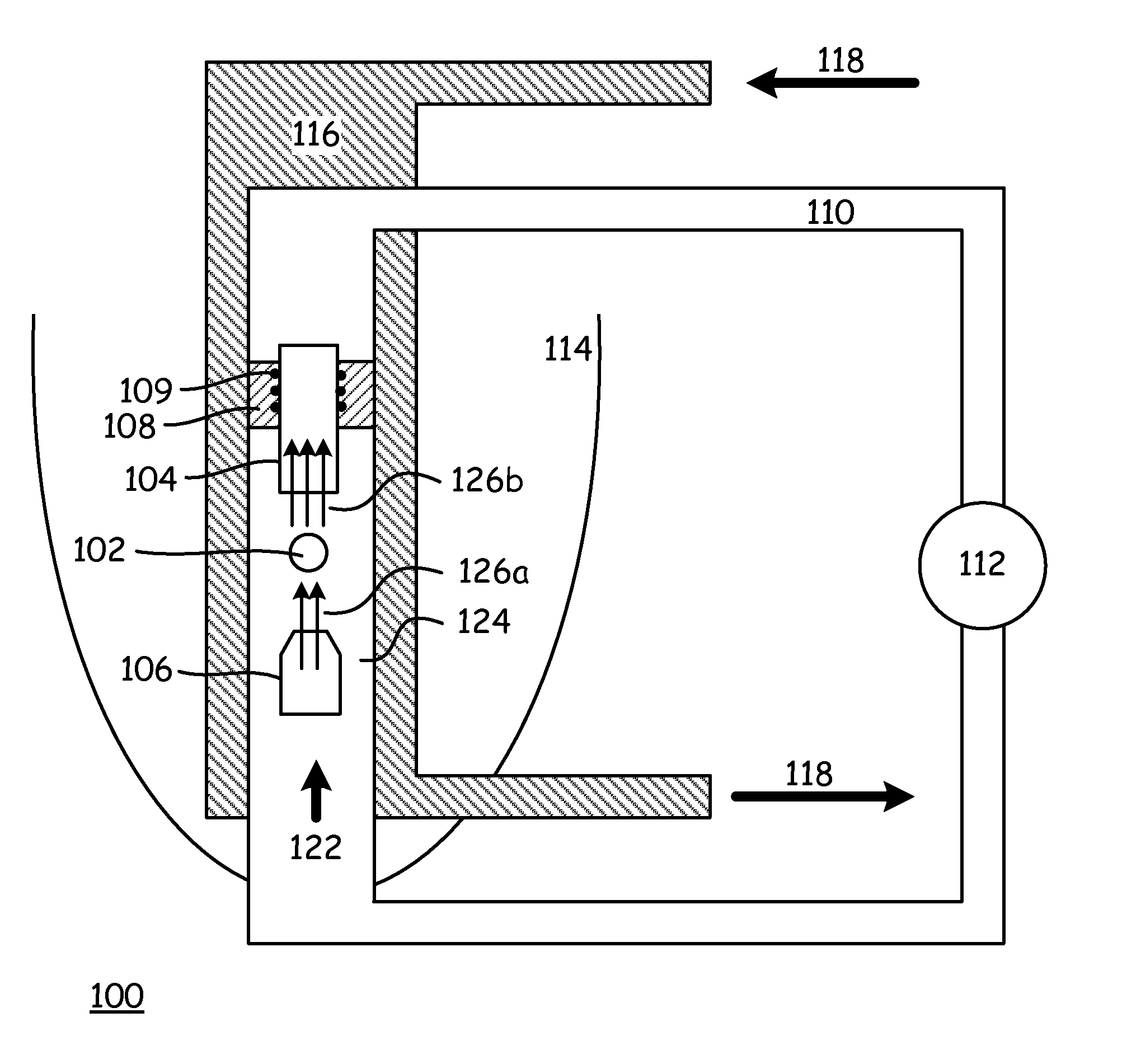
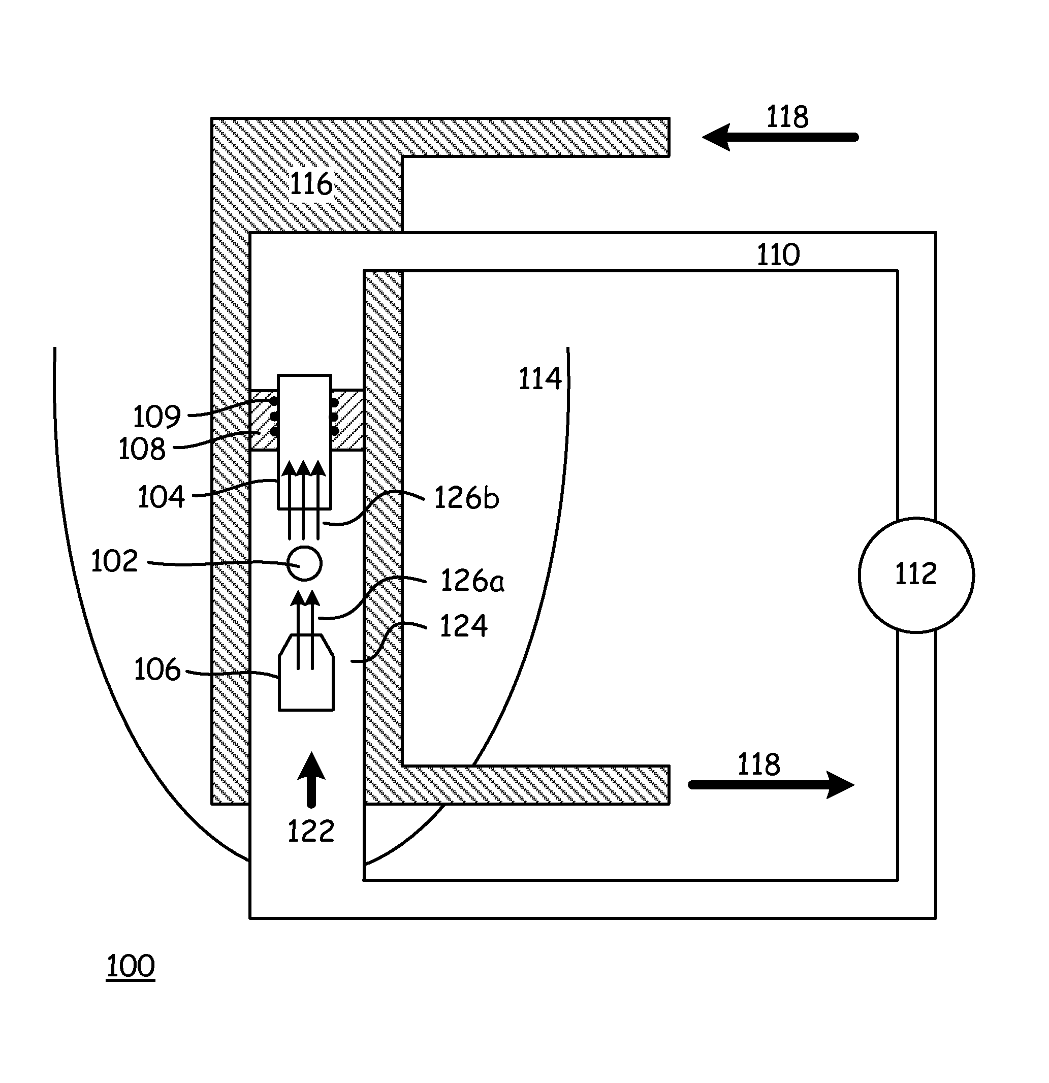
[0016]With reference now to the FIGURE, there is depicted a laser sustained plasma light source 100. One or more lasers (not depicted for clarity in the FIGURE) are directed into a focal point in a substantially optically transparent cell 124 in which there exists a gas volume 110. A plasma 102 is ignited from the gas volume 110 at the focal point. The ignition of the plasma 102 can be accomplished either by the lasers, by the electrodes 104 and 106, or by other means. The visible and other spectrum light (such as ultraviolet light) emitted by the plasma 102 is collected by the reflector 114, which focuses the light to a collection point, where it is provided to whatever use for which it is desired. The various aspects of these elements as described below tend to both increase the amount of light produced by the light source 100, and reduce the noise (variability) of the light produced by the light source 100.

[0017]In some embodiments, the cell 124 includes just the vertical section...


PUM


Abstract

A laser sustained plasma light source having a cell formed as a continuous tube with a circular cross section, a gas volume contained within the cell, at least one laser directed into the gas volume, for sustaining a plasma within the gas volume, the plasma producing a light, where the gas volume is heated as it leaves the plasma, cools as it circulates around the continuous tube of the cell, and reenters the plasma cooler than when it left the plasma and in a laminar flow, and a reflector for collecting the light and providing the light to a desired location.

Description

[0001]This application claims all rights and priority to U.S. provisional patent application Ser. No. 61 / 182,097 filed 2009 May 28.FIELD[0002]This invention relates to the field of integrated circuit fabrication. More particularly, this invention relates to laser-sustained plasma light sources, such as are used in various process steps during integrated circuit fabrication.INTRODUCTION[0003]The desire for integrated circuits having ever-higher transistor densities tends to drive a need in the industry to reduce the size of the structures from which those integrated circuits are created. Inspection of the patterned and unpatterned substrates on which such integrated circuits are fabricated requires unprecedentedly bright broad band light sources in the ultraviolet and visible region in order to provide the sensitivity and throughput that is required by the industry. Thus, there is a continual search for light sources that produce brighter lights at shorter wavelengths.[0004]One sourc...

Claims


Application Information

Patent Timeline
Patent Type & Authority Patents(United States)
IPC IPC(8): H01J1/02H01J61/52H01J61/54H01J61/28
CPCH01J61/28H01J61/52H01J61/54H01J61/545H01J65/042H01J1/025H01J23/033H05H1/4697H01J61/09
Inventor BEZEL, ILYASHCHEMELININ, ANATOLYZHAO, YANMINGDELGADO, GILDARDO R.
Owner KLA CORP
Why Eureka
Try Eureka