
Open water oil skimmer

a technology of oil skimmer and open water, which is applied in the field of oil spill recovery, can solve the problems of increasing the risk of oil spills, serious problems for the industries involved, and the spillage of crude oil and refined hydrocarbon products at sea, and achieve the effect of increasing or decreasing the buoyancy

Active Publication Date: 2015-08-11
CANTRELL JEFF +2
View PDF12 Cites 6 Cited by
  • Summary
  • Abstract
  • Description
  • Claims
  • Application Information

AI Technical Summary

Benefits of technology

The present invention is about an oil spill response technique that helps remove spilled oil from water bodies. It is a skimming device that uses adhesion to remove oil from water. It includes a housing and frame structure that is supported above the water. The skimmer has an adjustable wave damper to accommodate different sea conditions. It also has an induction pump and ballast-adjustable tanks to influence its buoyancy and wave riding. The technical effect of this invention is an improved oil spill response technique that helps to quickly and efficiently clean up oil spills in water.

Problems solved by technology

For many years, crude oil and refined hydrocarbon product spillages at sea have been a problem.
The environmental damage and clean up costs of large spills can present a serious problem for the industries involved.
As more crude oil and refined hydrocarbon products are being transported over longer distances by large tankers, and with the increase in off shore hydrocarbon exploration and production, the problem of dealing with spillages is likely to increase.
When compared with the problems of recovering spillages in quiet, calm seas, bays, harbors or rivers, the recovery of spillages in the open sea, particularly under adverse weather conditions, is clearly more difficult.
Frequently in the past, many types of spillage recovery equipment have only been effective in relatively calm conditions and were intended for short term operation.
Most of the presently-known equipment is of marginal use in harbors or relatively protected waters but is ineffective on the high seas.
Even in calm water, the prior art can be marginal at best.

Method used


Image

  • Open water oil skimmer
  • Open water oil skimmer
  • Open water oil skimmer

Examples


Embodiment Construction

[0017]In accordance with the present invention, a novel and improved oil spill skimmer is disclosed. The skimmer of the present invention designed for large scale, offshore oil spill skimming capable of high volume recovery of oil in the open sea, regardless of weather conditions. More particularly, the described equipment relates to an oil spill response technique used to readily remove spilled hydrocarbons from bodies of water. In the broadest context, the oil spill skimmer equipment of the present invention consists of components configured with respect to each other so as to attain the desired objective.

[0018]The present invention is now exemplified by a particular embodiment which is illustrated in the accompanying drawings.

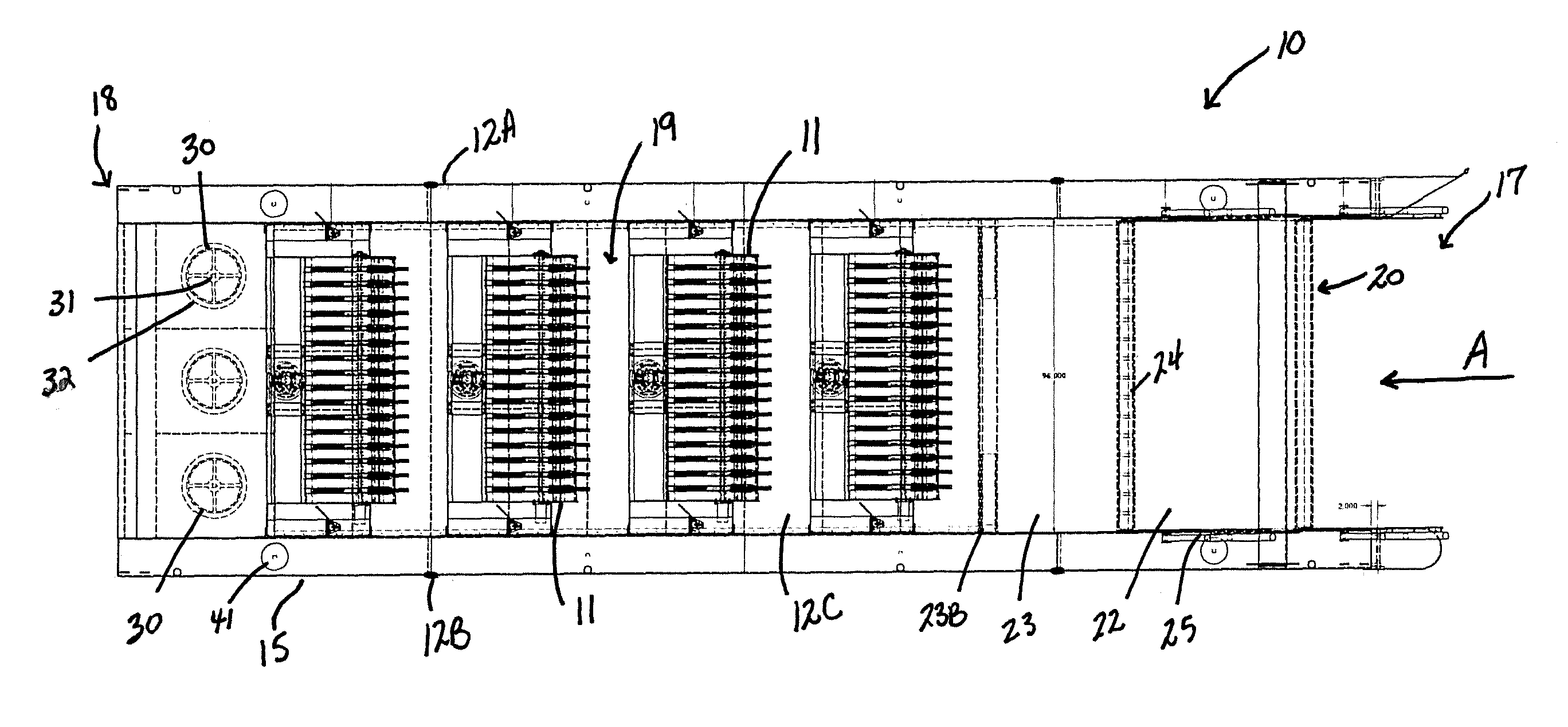
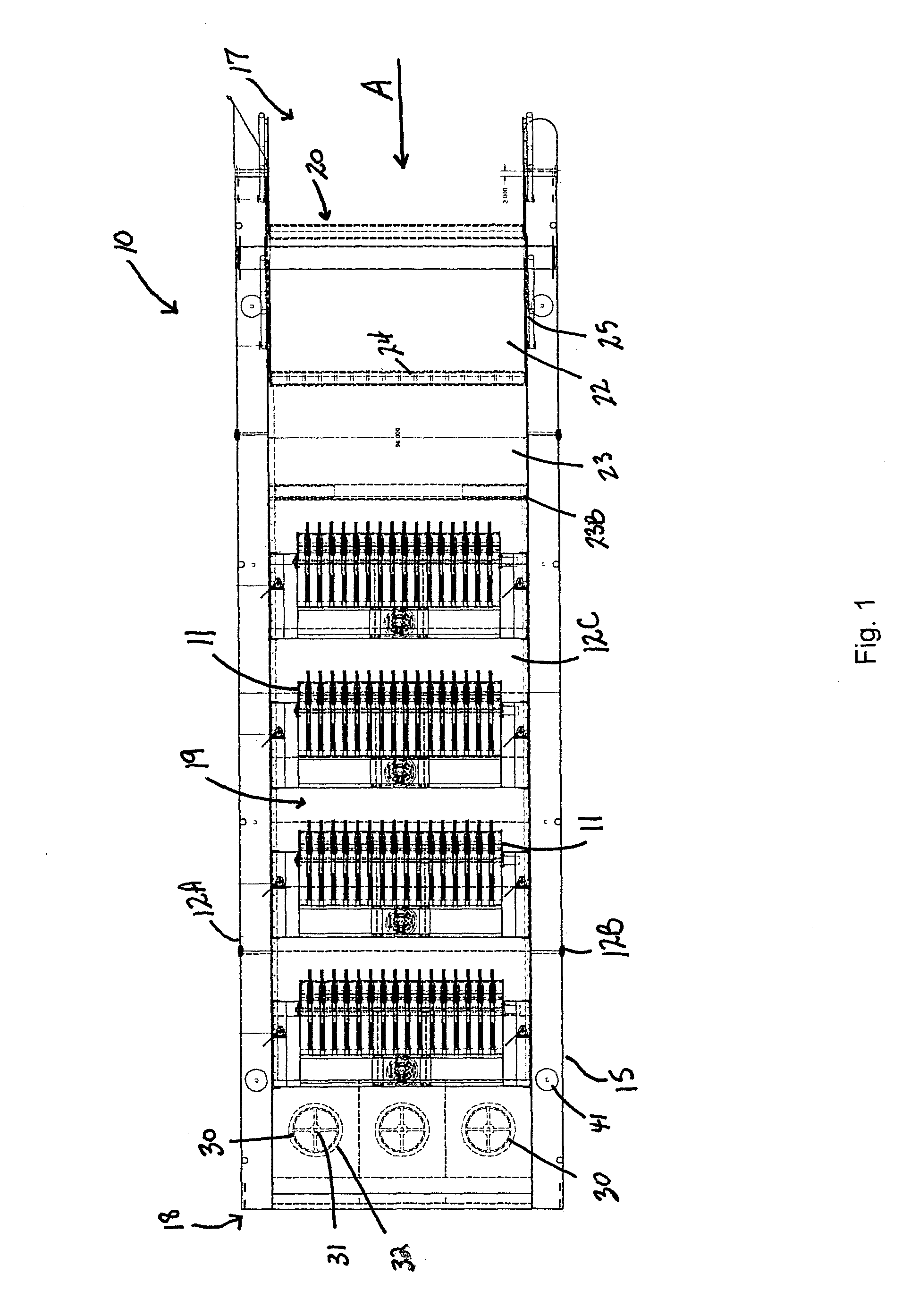
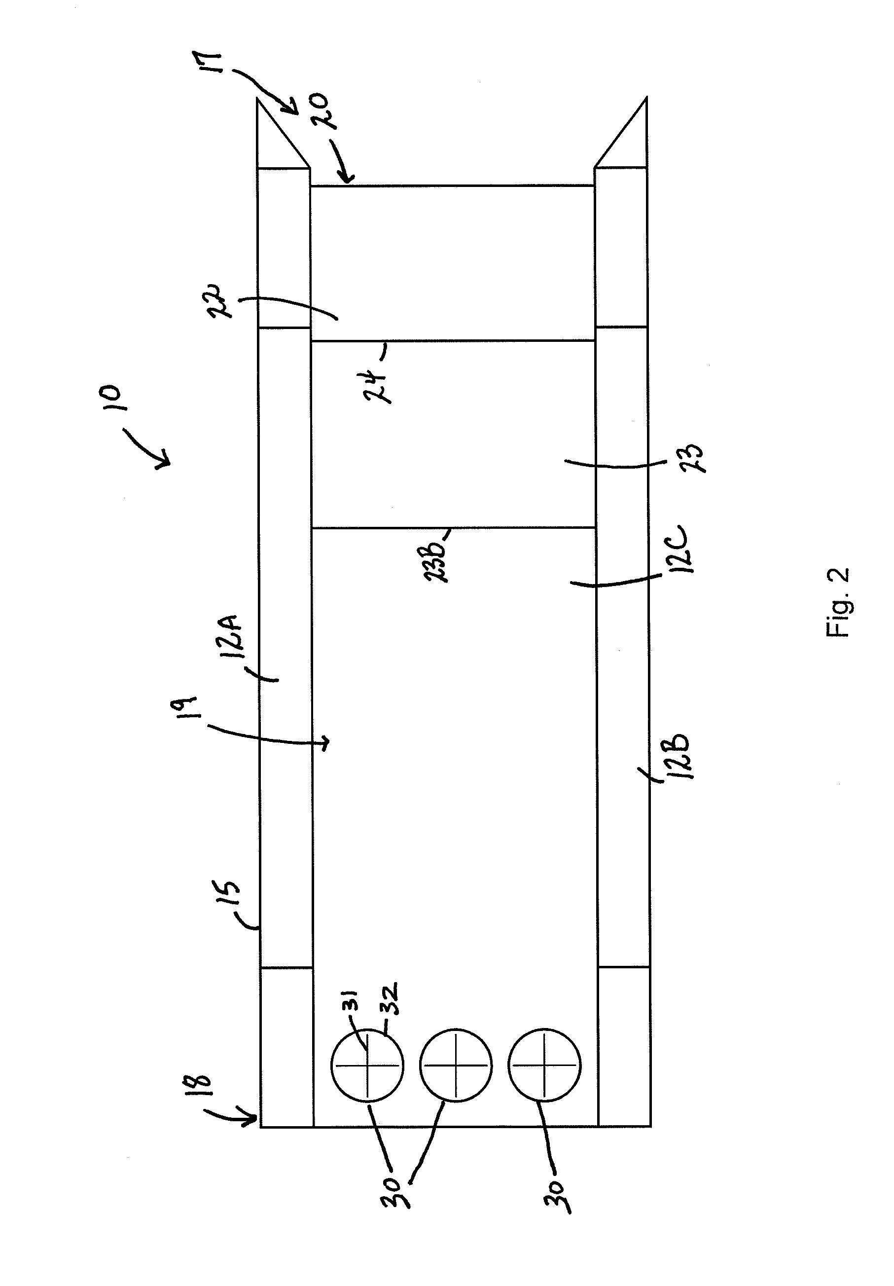
[0019]The oil spill skimmer of this application is shown generally designated as numeral 10. The skimmer 10 has certain features that are well known in the art and as such those features will not be described here. In this embodiment, the skimmer 10 is prima...


PUM

PropertyMeasurementUnit
buoyancyaaaaaaaaaa
speedaaaaaaaaaa
volumeaaaaaaaaaa

Abstract

An oil spill skimmer for removing heavy hydrocarbons from bodies of water, having a plurality of oleophilic oil separation devices, a housing and frame structure that is suitably supported above a body of water, an adjustable wave damper supported by the housing at a front of the skimmer, an at least one flow inducer supported by the housing at a rear of the skimmer, and ballast-adjustable tanks. The at least one flow inducer for inducing inflow such that water is pulled at the front of the skimmer and directed out a bottom of the skimmer while collecting the spillage in a collection area. The ballast can be moved in and out of the tanks to increase or decrease buoyancy and influence the wave riding or wave heave of the skimmer.

Description

CROSS REFERENCES TO RELATED APPLICATIONS[0001]U.S. Provisional Application for Patent No. 61 / 576,734, filed Dec. 16, 2011, with title “Open Water Oil Skimmer” which is hereby incorporated by reference. Applicant claims priority pursuant to 35 U.S.C. Par. 119(e)(i).[0002]Statement as to rights to inventions made under federally sponsored research and development: Not ApplicableBACKGROUND OF THE INVENTION[0003]1. Field of the Invention[0004]The present invention relates to oil spill recovery, and more particularly to large scale, offshore and nearshore oil spill skimming equipment capable of high volume recovery of oil in the open sea, regardless of weather conditions.[0005]2. Brief Description of Prior Art[0006]For many years, crude oil and refined hydrocarbon product spillages at sea have been a problem. The environmental damage and clean up costs of large spills can present a serious problem for the industries involved. As more crude oil and refined hydrocarbon products are being t...

Claims


Application Information

Patent Timeline
Patent Type & Authority Patents(United States)
IPC IPC(8): E02B15/04B01D21/00B63B35/32E02B15/10C02F1/40C02F101/32C02F103/00C02F103/08
CPCE02B15/048E02B15/046B63B35/32B01D21/0027C02F1/40C02F2101/32C02F2103/007C02F2103/08E02B15/102B63B2207/02Y02A20/144Y02A20/204
Inventor CANTRELL, JEFFSMITH, PAULMORGAN, JUSTIN
Owner CANTRELL JEFF
Learn More