Differential phase-contrast imaging with improved sampling

a phase-contrast imaging and sampling technology, applied in the field of x-ray imaging technology, can solve the problems of inability to detect the interference pattern generated by only using a phase grating, the spatial resolution of a grating-based differential phase-contrast imaging system is typically limited, and the imaged inner structure of the object is missing detail, so as to improve the spatial resolution of the differential phase-contrast projection, increase the individual pixel area, and improve the spatial resolution of the differential phase-con

Inactive Publication Date: 2015-08-11
KONINK PHILIPS ELECTRONICS NV
View PDF11 Cites 11 Cited by
  • Summary
  • Abstract
  • Description
  • Claims
  • Application Information

AI Technical Summary

Benefits of technology

[0016]An aspect of the present invention may be seen as providing means for overcoming the limit of spatial resolution directly depending on the physical size of a detector pixel element, thus increasing spatial resolution beyond the actual size of the detector pixel element. This may allow improving the spatial resolution of the differential phase-contrast projection while employing a current X-ray detector or while maintaining the spatial resolution of the differential phase-contrast projection relaxing the requirements of the spatial resolution of the detector, e.g., by increasing the individual pixel area of an individual detector pixel element.
[0019]In particular, it may be beneficial to increase the resolution of an apparatus for phase-contrast imaging without further reducing the area of an individual pixel element.

Problems solved by technology

However, an object to be examined may provide only minor differences when attenuating the X-ray radiation, resulting in a relatively uniformly attenuated X-ray image having low contrast, thus lacking detail of the imaged inner structure of the object.
However, an interference pattern generated by only employing a phase grating may be too small to be detectable with a current X-ray detector, due to a lack of spatial resolution of the X-ray detector.
The spatial resolution of a grating based differential phase-contrast imaging system is typically limited by the size of the focal spot of the X-ray source and the size of a single detector pixel element.
While differential phase-contrast imaging may provide enhanced image information over transmission X-ray imaging taking into account attenuation only, the spatial resolution of the so obtained image information may be considered to still be limited by the individual detector pixel elements and their respective size.

Method used


Image

  • Differential phase-contrast imaging with improved sampling
  • Differential phase-contrast imaging with improved sampling
  • Differential phase-contrast imaging with improved sampling

Examples


Embodiment Construction

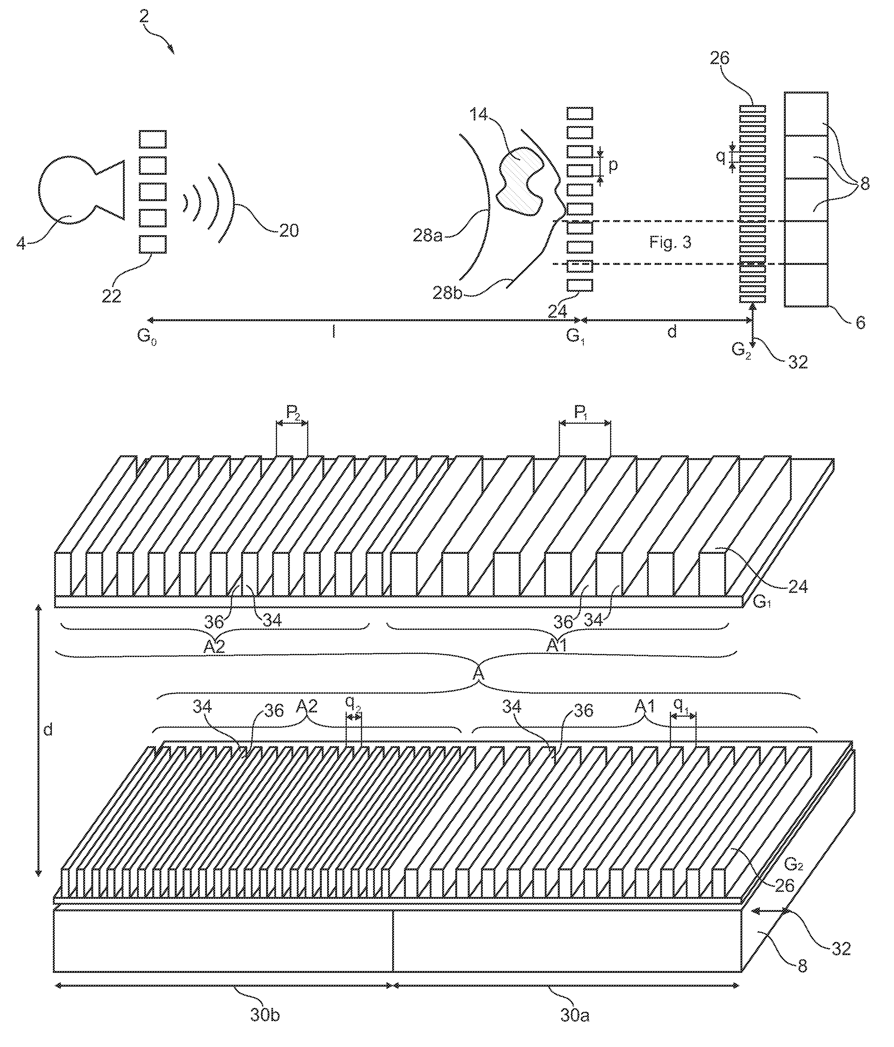
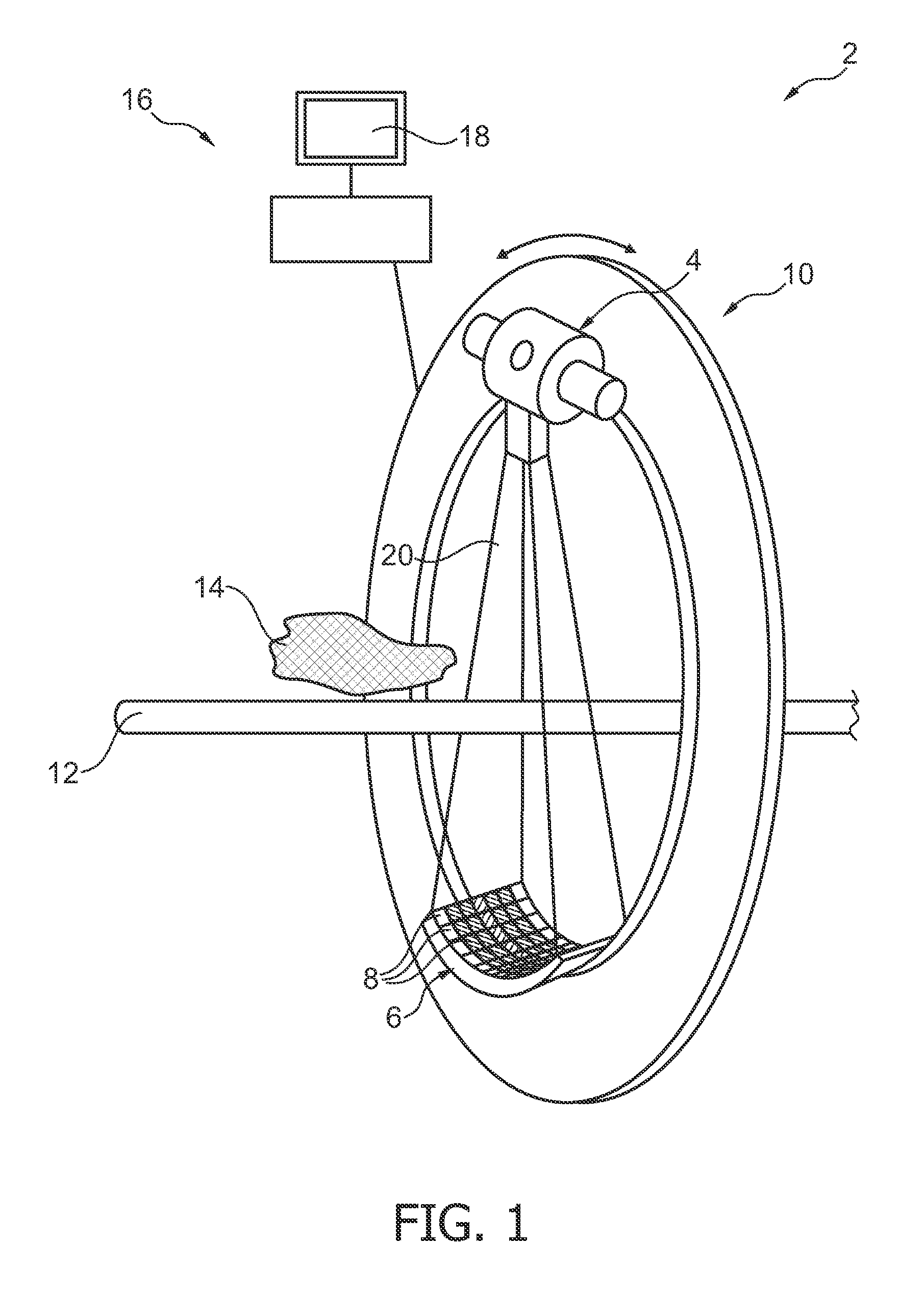
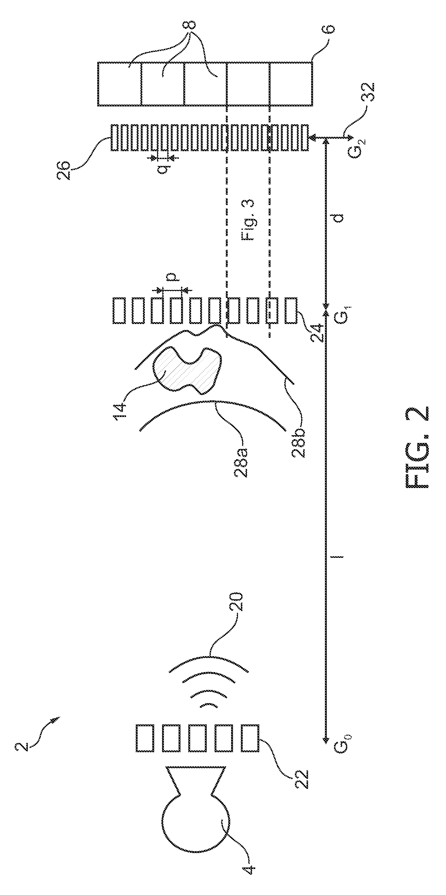
[0027]One aspect of the present invention may be seen as employing a phase grating and an analyzer grating having a non-uniform or varying pitch structure with regard to each detector pixel. In particular, each of the phase grating and the analyzer grating may be seen as being divided in two individual areas with each individual area corresponding to the area and / or size of a single detector pixel element of the X-ray detector.

[0028]Within each area corresponding to a single detector pixel element, the grating structure of the phase grating and the analyzer grating may be a non-uniform grating structure. The non-uniform grating structure may be seen as employing at least two individual grating pitches for each detector pixel element.

[0029]The grating structure of each grating element may be seen as comprising individual barrier elements, each forming a barrier region, spaced apart from one another, thus forming a trench region between the barrier elements. Preferably, the trench reg...


PUM

PropertyMeasurementUnit
areaaaaaaaaaaa
sizeaaaaaaaaaa
phase contrast imagingaaaaaaaaaa

Abstract

The present invention relates to differential phase-contrast imaging of an object. For increasing spatial resolution of an X-ray imaging system (2) the size of a detector pixel element (8) may be considered a limiting factor. Accordingly, it may be beneficial to increase the resolution of an apparatus (38) for phase-contrast imaging without further reducing the area of an individual pixel element (8). Accordingly, an apparatus (38) for phase-contrast imaging with improved sampling is provided, comprising an X-ray source (4), a first grating element G1 (24), a second grating element G2 (26) and an X-ray detector element (6) comprising a plurality of detector pixel elements (8), each detector pixel element (8) having a pixel area A. An object to be imagined (14) is arrangeable between the X-ray source (4) and the X-ray detector element (6). The first grating element G1 (24) as well as the second grating element G2 (26) are arrangeable between the X-ray source (4) and the X-ray detector element (6). The X-ray source (4), the first grating element G1 (24), the second grating element G2 (26) and the X-ray detector (6) are operatively coupled for acquisition of a phase-contrast image of the object (14). At least one of the first grating element G1 (24) and the second grating element G2 (26) comprise a first area A1 having a first grating pitch p1 and a second area A2 having a second grating pitch p2 different from the first grating pitch.

Description

FIELD OF THE INVENTION[0001]The present invention relates to X-ray imaging technology in general.[0002]More particularly, the present invention relates to differential phase-contrast imaging.[0003]In particular, the present invention relates to an apparatus for phase-contrast imaging with improved sampling, an X-ray system comprising an apparatus according to the present invention as well as the use of an apparatus according to the present invention in one of an X-ray system and a CT system.BACKGROUND OF THE INVENTION[0004]When acquiring an X-ray image, an object to be examined, e.g. a patient, is arranged between an X-ray generating device and an X-ray detector. X-ray radiation emanating from the X-ray generating device is penetrating the object to be examined, subsequently arriving at the X-ray detector. The object to be examined, situated in the path of the X-ray radiation is spatially attenuating the X-ray beam, depending on the specific tissue structure within the object. The X...

Claims


Application Information

Patent Timeline
Patent Type & Authority Patents(United States)
IPC IPC(8): A61B6/00G01N23/04G21K1/02G21K1/06A61B6/03
CPCA61B6/032A61B6/4035A61B6/4291A61B6/484G21K1/02G01N23/04G21K1/067G21K2207/005G01N23/041
Inventor KOEHLER, THOMAS
Owner KONINK PHILIPS ELECTRONICS NV
Why Eureka
Try Eureka