
Apparatus for filtering and/or conditioning and/or purifying a fluid such as water, and interface thereof for providing water boiler expansion pressure relief

a technology for purifying fluids and filters, applied in separation processes, filtration separation, treatment involving filtration, etc., can solve the problems of contaminated aircraft drinking water systems/supplies, inability to legally refer to filters as microorganism purifiers, and high cost of space in galley and lavatory compartments

Active Publication Date: 2015-08-18
GENERAL ECOLOGY
View PDF4 Cites 26 Cited by
  • Summary
  • Abstract
  • Description
  • Claims
  • Application Information

AI Technical Summary

Benefits of technology

The invention provides an apparatus and interface for filtering and purifying water in a water distribution system, such as for aircraft. The apparatus allows for the expansion pressure of the water boiler to be directed backward through the water lines of the system, while preventing contaminated water from flowing back into the canister where the water is being filtered and purified. This helps to prevent contamination of the water and ensures safe water quality.

Problems solved by technology

There are many possible opportunities for aircraft drinking water systems / supplies to become contaminated with microorganisms even if hygienically safe when loaded aboard an aircraft.
's Structured Matrix™ microfilters or simple, fine, or coarse carbon and / or sediment systems, may be sophisticated, but such filters cannot legally be referred to as microbiological purifiers before being verified that they meet the EPA Guide Standard Protocol for Microbiological Purifiers.
Space in galley and lavatory compartments is expensive and severely limited.
Accordingly, water filter / purifier units usually are installed in “out of the way”, often difficult to access locations often behind other more readily accessible equipment and bulkheads.
The sanitation process requires time and labor intensive removal of filtration / purification cartridges from the water filter / purifier units installed in galleys, fountains, and lavatories throughout the aircraft prior to the sanitation process.
Even though sanitization is recognized as effective, typically because of the relatively high cost of the sanitizing process and the revenue lost due to the downtime of the aircraft during the sanitizing process, sanitization is performed infrequently—possibly every six months or at a convenient “A Check” or more extensive maintenance intervals when other maintenance is carried out.
Several hours may be required to sanitize an aircraft resulting in costs averaging upwards to hundreds of dollars per unit.
Although the very latest filter / purifier units include automatic vacuum breaks and venting, most aircraft units require manual actuation often resulting in inadequate water draining and filling.
Also, under the proposed EPA regulations, it is likely that accessing and actuating manual vents and vacuum breaks, sometimes previously ignored, may become a significantly higher maintenance cost item due to difficult access to the water filter / purifier units and aircraft “out of service” revenue costs.
Therefore, a small number of bacteria may quickly reach infectious concentrations in water intended to be consumed, especially downstream of improperly installed / serviced filters / purifiers employed to remove chlorine, foul tastes, and odors.
Further, water filter / purifier units installed in semi-remote locations along the water distribution system often require longer than desired distribution lines to specific service points (e.g., locations where the water is discharged from the water distribution system).
These distribution lines provide unnecessary opportunities for previously purified water to be recontaminated from inadvertent inoculation, short term bacteria multiplication or biofilm formation / shedding that may have taken place in such distribution lines downstream of the water filter / purifier units.
If water boiler expansion pressure builds up to a dangerous level due to a water boiler overheating, and protection against backflow of water through the water filter / purifier units is provided, the water boiler expansion pressure created by the water boiler overheating creates a risk of extremely hot water blowing back along the water distribution lines between the water boiler and a water filter / purifier unit, with the pressure being released by opening a faucet, such as a cold water faucet, positioned along the water distribution lines between the water boiler and the water filter / purifier unit upstream of the water boiler, resulting in the person that opened the faucet being injured by scalding hot water.
Removing the backflow protection to provide some water boiler expansion pressure relief in the potable water distribution system creates a risk that the structure of the filtration / conditioning / purification medium (e.g., a filtration / conditioning / purification cartridge) of a water filter / purifier unit may be damaged if exposed to such water boiler expansion pressure.
Moreover, removing the backflow protection creates a risk that water contaminated downstream of the water filter / purifier unit may backflow into the water filter / purifier unit and contaminate the portion of the water filter / purifier unit downstream of the filtering / conditioning / purifying medium of the water filter / purifier unit, thereby causing water exiting the outlet port of the filter / purifier unit to be contaminated, which would create a health risk to passengers from bacteria, viruses, and the like being transferred from contaminated water from the water distribution system.

Method used


Image

  • Apparatus for filtering and/or conditioning and/or purifying a fluid such as water, and interface thereof for providing water boiler expansion pressure relief
  • Apparatus for filtering and/or conditioning and/or purifying a fluid such as water, and interface thereof for providing water boiler expansion pressure relief
  • Apparatus for filtering and/or conditioning and/or purifying a fluid such as water, and interface thereof for providing water boiler expansion pressure relief

Examples


Embodiment Construction

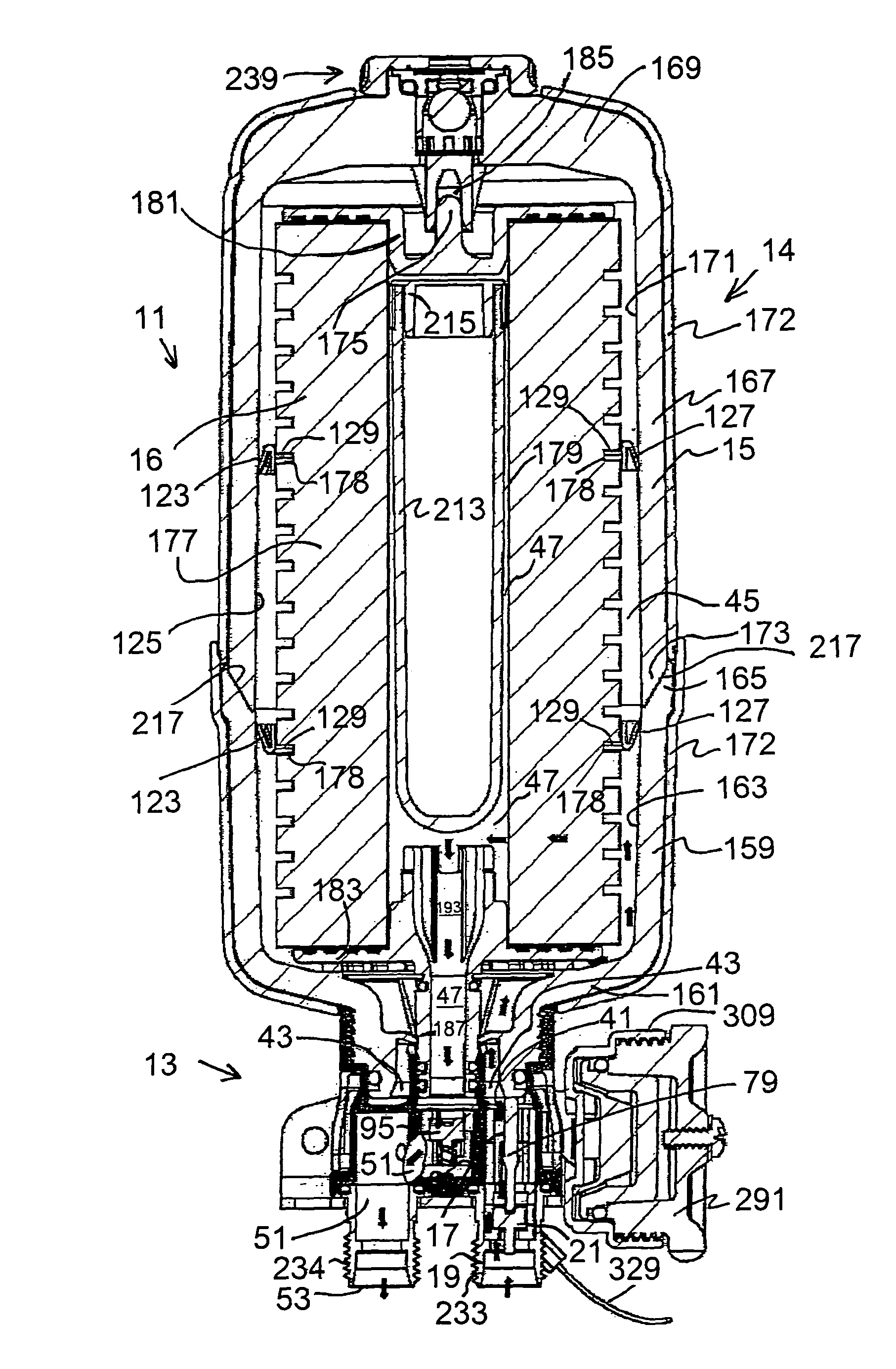
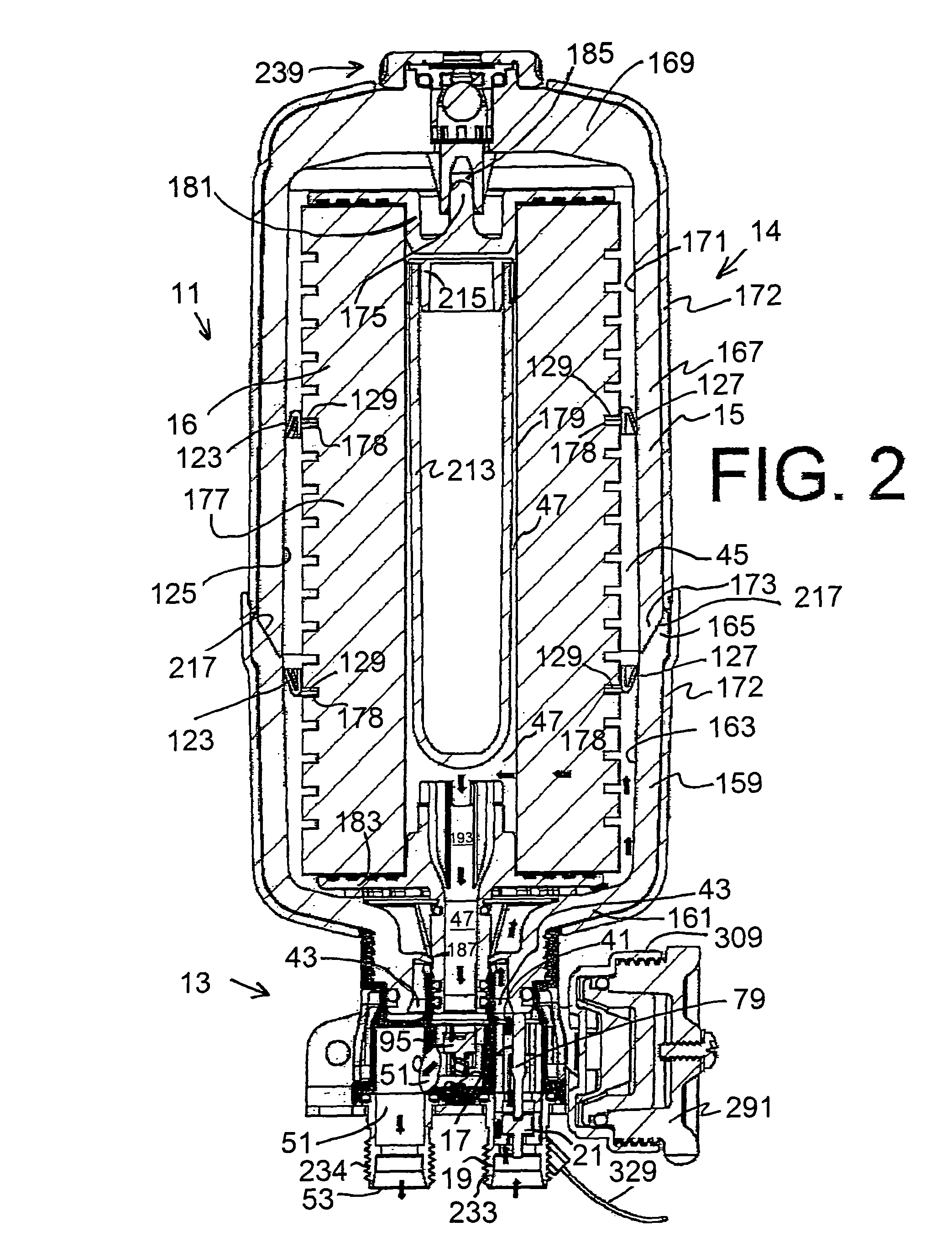
[0043]Turning now to the drawings, there is shown the inventive apparatus 11 for filtering and / or conditioning and / or purifying a fluid, such as water. (Purification, per EPA regulations, requires performance meeting the EPA Guide Standard Protocol for Microbiological Purifiers; filtration and conditioning may be almost anything else that is useful, such as taste and odor removal, scale control, etc.)

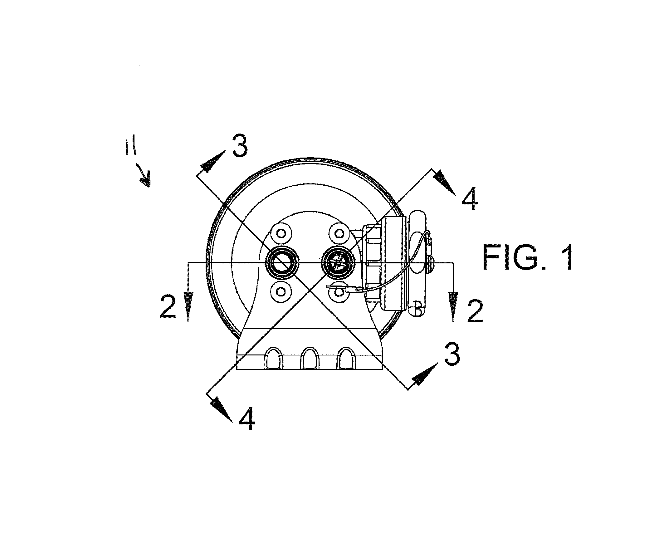
[0044]Referring particularly to FIGS. 1 to 11, and more particularly to FIG. 29, apparatus 11 includes an interface 13 (also known as an automatic valving unit or a valve head or manifold) for a filtration / purification canister 14 comprising a pressure vessel 15 that holds a cartridge 16, or loose media, or the like for filtering and / or conditioning and / or purifying a fluid, such as water. The interface 13 automatically provides for fluid flow into the pressure vessel 15 when the pressure vessel 15 is connected to the interface 13, and automatically discontinues fluid flow from the inte...


PUM

PropertyMeasurementUnit
survival temperatureaaaaaaaaaa
expansion pressureaaaaaaaaaa
pressureaaaaaaaaaa

Abstract

An apparatus for filtering water has an interface and a filtration / purification canister removably mountable onto the interface. Connecting the canister to the interface automatically opens a check valve in the interface to permit water to flow from the interface into and through the canister, and then back to and through the interface to an outlet port. Disconnecting the canister from the interface automatically closes the check valve, stopping the flow of water. The interface provides for water boiler expansion pressure relief, while guarding against any water contaminated downstream of the apparatus from backflowing into the filtration / purification canister and contaminating the portion of the filtration / purification canister downstream of the filter / conditioning / purifying medium held within the filtration / purification canister and thereby causing water exiting the outlet port of the filtration / purification canister to be contaminated.

Description

FIELD OF THE INVENTION[0001]This invention relates to apparatuses for filtering and / or conditioning and / or purifying a fluid such as water, and more particularly concerns such apparatuses that use a pressure vessel holding a cartridge, loose media, or the like for filtering and / or conditioning and / or purifying a fluid such as water which are used in potable water distribution systems, such as potable water distribution systems for aircraft.BACKGROUND OF THE INVENTION[0002]Adequate hydration is particularly important for comfortable air travel, especially aboard modern, very large, long range aircraft capable of flights of 20 or more hours duration. Typically, water is distributed to galleys, lavatories, and drinking water outlets of the aircraft to provide drinking water to passengers, to provide water for food and beverage preparation, and to provide water for personal hygiene (e.g., face and hand rinsing, teeth cleaning, etc.) during flights. Aircraft typically are crowded with th...

Claims


Application Information

Patent Timeline
Patent Type & Authority Patents(United States)
IPC IPC(8): B01D21/20B01D35/18E03B1/00F16K51/00B01D35/147B01D24/38C02F1/00E03B7/07
CPCF16K51/00B01D35/147B01D24/38C02F2301/02C02F1/001B01D2201/167E03B7/078B01D2201/04B01D2201/303B01D35/153C02F1/003C02F2201/001C02F2201/005C02F2201/006B01D29/11B01D29/88B01D35/02B01D35/30B01D2201/16C02F2303/04
Inventor WILLIAMS, RICHARD T.BEISWENGER, CARL
Owner GENERAL ECOLOGY
Learn More