Ceramic electronic component

a ceramic electronic component and ceramic technology, applied in the direction of fixed capacitor details, capacitors, fixed capacitors, etc., can solve the problems of difficult to increase the positional precision of internal electrodes, and difficult to increase the performance of laminated ceramic electronic components, so as to achieve the effect of significantly improving the performance of ceramic electronic components

Active Publication Date: 2015-08-18
MURATA MFG CO LTD
View PDF17 Cites 1 Cited by
  • Summary
  • Abstract
  • Description
  • Claims
  • Application Information

AI Technical Summary

Benefits of technology

[0006]Preferred embodiments of the present invention provide a ceramic electronic component having improved performance.
[0014]According to various preferred embodiments of the present invention, the performance of the ceramic electronic component is significantly improved.

Problems solved by technology

However, in the case of the laminated ceramic capacitor disclosed in JP 2006-332601 A, it is difficult to increase the positional precision for the internal electrodes.
Therefore, it is difficult to increase the performance of the laminated ceramic electronic component.

Method used


Image

  • Ceramic electronic component
  • Ceramic electronic component
  • Ceramic electronic component

Examples


Embodiment Construction

[0019]Non-limiting examples of preferred embodiments of the present invention will be described below. However, the following preferred embodiments are merely described by way of example. The present invention is not limited in any way to the following preferred embodiments.

[0020]In addition, in the drawings, members which have substantially the same functions are referenced by the same symbols. In addition, the drawings are schematic illustrations. The dimensional ratios and proportions of the elements shown in the drawings may be different from the dimensional ratios and proportions of the real elements in some cases. The dimensional ratios and proportions of the elements may be also different between the drawings in some cases. The specific dimensional ratios and proportions of the elements should be determined in view of the following description.

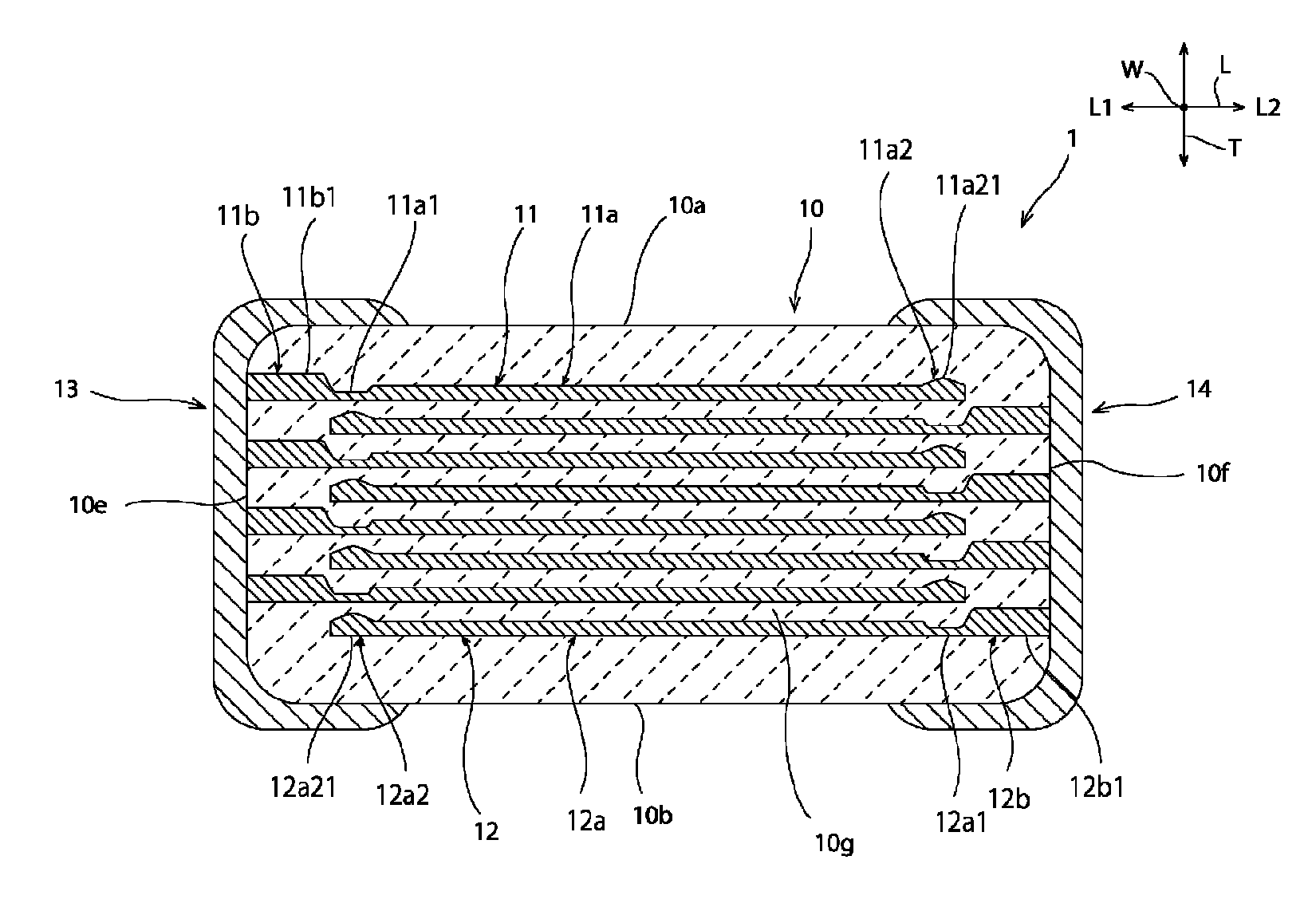
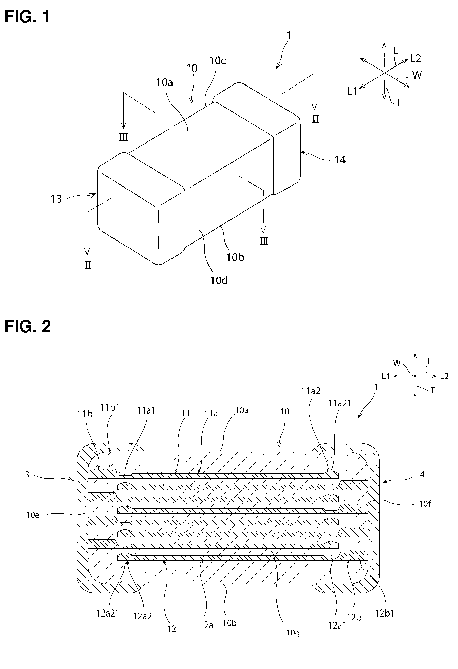
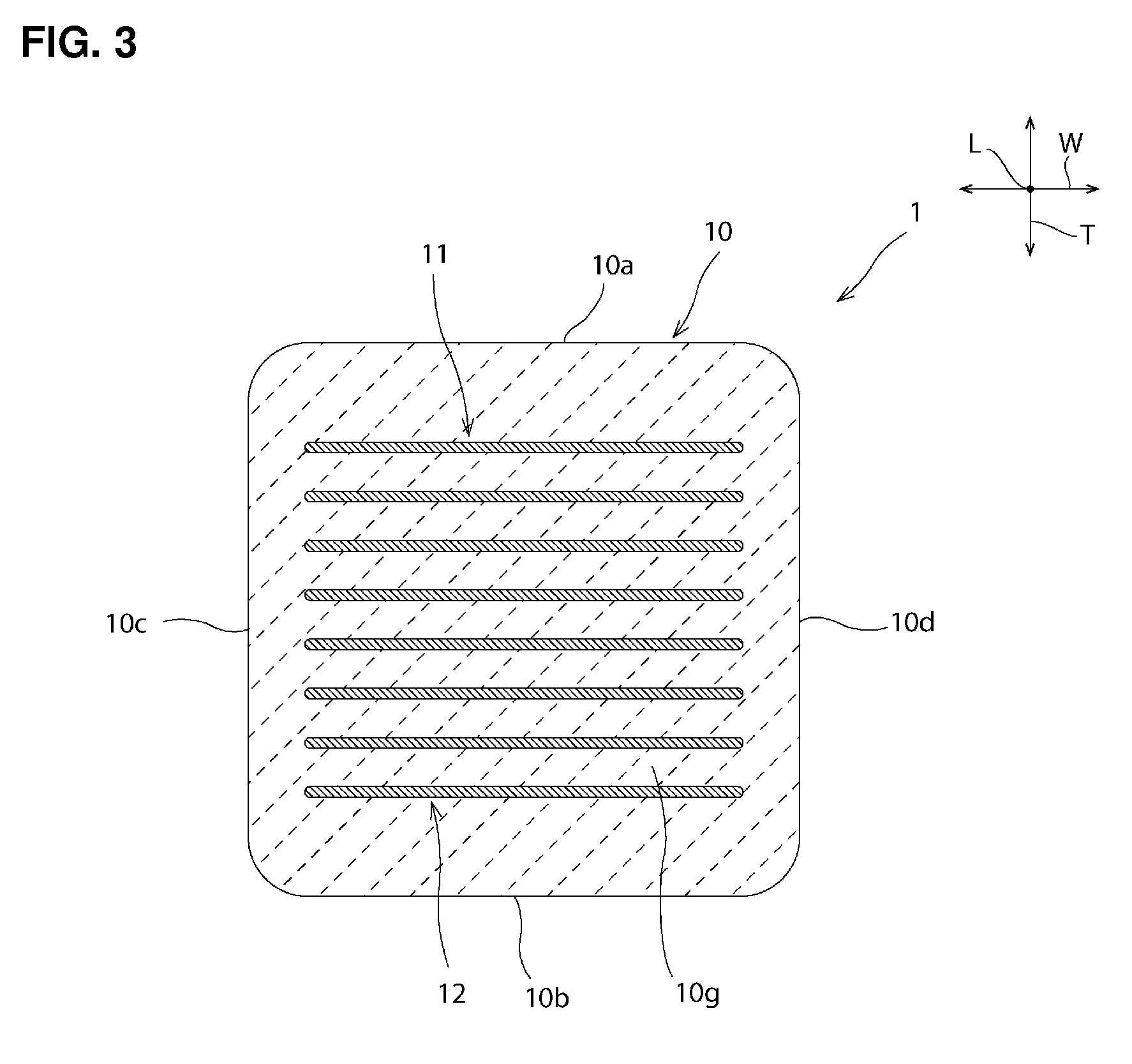
[0021]FIG. 1 is a schematic perspective view of a ceramic electronic component 1 according to a preferred embodiment of the present in...


PUM

PropertyMeasurementUnit
thickaaaaaaaaaa
thicknessaaaaaaaaaa
conductiveaaaaaaaaaa

Abstract

A ceramic electronic component includes a first internal electrode that includes a first opposed section and a first extraction section. The first opposed section is opposed to a second internal electrode with a ceramic layer interposed therebetween. The first extraction section is located closer to a first end surface than the first opposed section. The first extraction section includes a first thick section. The first thick section is thicker than a first central section of the first opposed section. The first opposed section includes a first base end section opposed to a second tip section of the second internal electrode closer to the first end surface, with the ceramic layer interposed therebetween, and the first base end section includes a first thin section. The first thin section is thinner than the first central section.

Description

BACKGROUND OF THE INVENTION[0001]1. Field of the Invention[0002]The present invention relates to a ceramic electronic component.[0003]2. Description of the Related Art[0004]Conventionally, ceramic electronic components, such as ceramic capacitors, have been used for various applications. For example, JP 2006-332601 A discloses, as an example of the components, a laminated ceramic capacitor in which an internal electrode is thicker in an electrode extraction section than in a capacitance generation section. In the laminated ceramic capacitor disclosed in JP 2006-332601 A, the relatively thick electrode extraction section has a partial overlap with the relatively thin capacitance generation section in the length direction.[0005]From the perspective of increasing the performance of ceramic electronic components, it is important to provide internal electrodes with high positional precision. However, in the case of the laminated ceramic capacitor disclosed in JP 2006-332601 A, it is diff...

Claims


Application Information

Patent Timeline
Patent Type & Authority Patents(United States)
IPC IPC(8): H01G4/005H01G4/30H01G4/012H01G4/232
CPCH01G4/30H01G4/012H01G4/232H01G4/2325
Inventor HAMADA, KUNIHIKO
Owner MURATA MFG CO LTD
Why Eureka
Try Eureka