Provision of an output voltage from a wide range variable and low input voltage

Inactive Publication Date: 2015-08-18
PULS GMBH
View PDF9 Cites 1 Cited by
  • Summary
  • Abstract
  • Description
  • Claims
  • Application Information

AI Technical Summary

Benefits of technology

The present invention provides a circuit arrangement that can reliably supply a sufficient output voltage and current to critical consumers, even at very low input voltages. The circuit arrangement is useful in situations where the input voltage is too low or the output voltage and current need to be increased in case of failure. The circuit arrangement can operate at both high and low input voltages and can handle fluctuating input voltages without losing efficiency. This simplifies the incorporation of the circuit arrangement into other electronic circuits. The circuit arrangement includes a first switching converter and a second switching converter, which can start at low input voltages and have low losses in operation. The second switching converter can be adapted to have a higher minimum driving voltage but lower conducting state losses and switching losses compared to the first switching converter. This allows the circuit arrangement to handle fluctuating input voltages and to provide a reliable output.

Problems solved by technology

The energy supply capabilities of such current supply units are limited in any case.
The aforementioned solutions have the disadvantage that they either require a) comparably elaborate additional electronics and, in addition to this, additional cabling or b) regular maintenance.
In case of c), the functionality is limited to a short period of time and in the case of d), to certain environmental conditions.
Furthermore, the solutions c), d) and especially e) are limited in their energy supply capabilities and thus cannot be employed in many cases.
If one tries, on the basis of known circuits for supplying consumers from very small voltages, to find a solution, which is suitable for both preceding cases at the same time, the same problems arise again and again.
These circuits are furthermore generally only laid out for smaller currents than about 1 A and smaller voltages than about 20V—in any case not suitable to fulfil all requirements with regard to the input voltage stability, output voltage stability and the current supply capability at the same time, without adding a considerable amount of additional electronics.

Method used


Image

  • Provision of an output voltage from a wide range variable and low input voltage
  • Provision of an output voltage from a wide range variable and low input voltage
  • Provision of an output voltage from a wide range variable and low input voltage

Examples


first embodiment

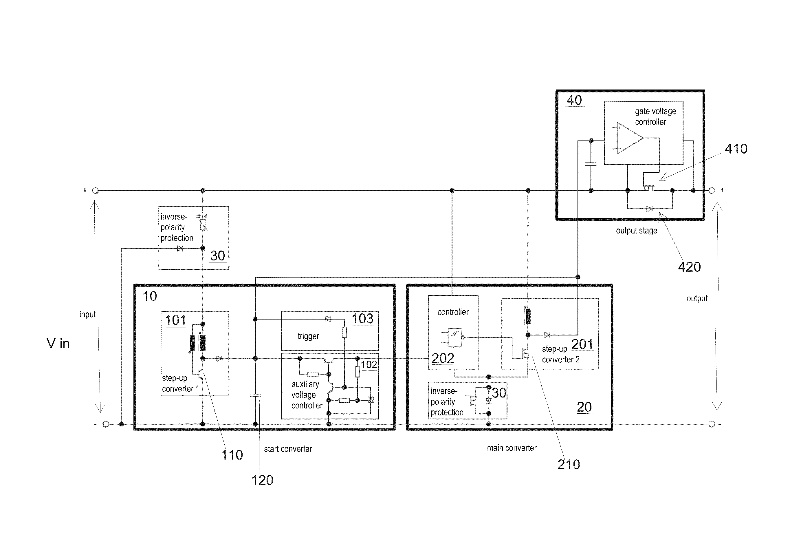
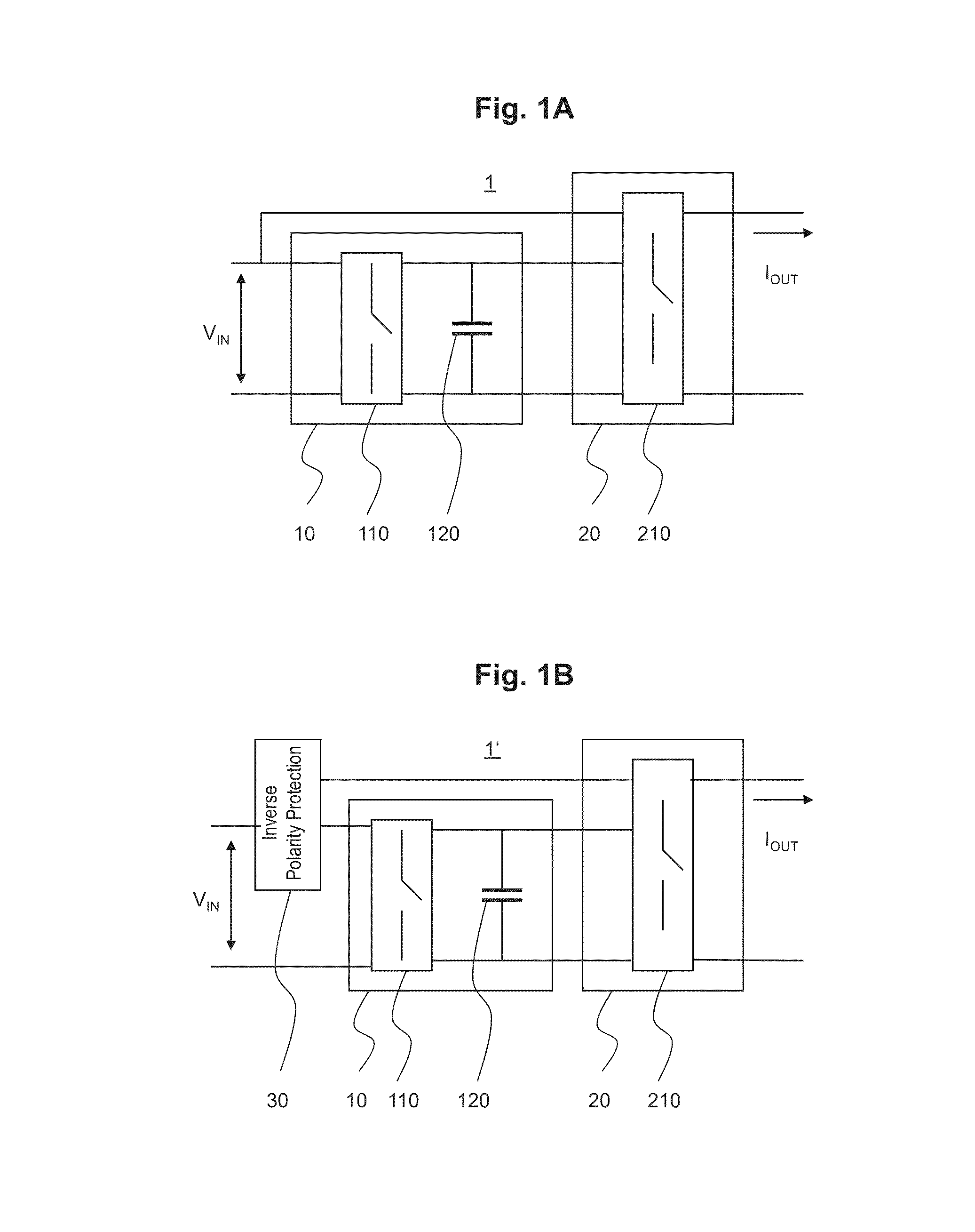
[0027]FIG. 1A shows a circuit arrangement 1 in accordance with the present invention. In accordance with the present invention, the circuit arrangement 1 comprises a first switching converter 10 (also called start converter) and a second switching converter 20 (also called main converter). The start converter 10 generates, from the available input voltage Vin, an auxiliary voltage for the main converter 20. The start of the main converter 20 takes place at a sufficiently large auxiliary voltage. In this regard, the function of the main converter 20 can consist in the generation of a supply voltage for a further consumer, such as an output stage of a redundancy module or any other control circuit. In this manner, the main converter 20 can, when required, ensure such auxiliary voltage supply, although the available input voltage Vin is not sufficient for starting the main converter 20.

[0028]Here, the start converter 10 comprises a storage element 120, such as a capacitor, and a first ...

second embodiment

[0029]FIG. 1B shows a circuit arrangement in accordance with the present invention. In addition to the circuit arrangement 1 of FIG. 1A, an inverse-polarity-protection 30 is provided which, in case of a inverse polarity of the input voltage, constitutes an effective protection of the remaining component groups and consumers. This inverse-polarity protection 30 can become effective in case of an operating error or a switching of the polarity when connecting to the input voltage—or in case of any other inverse-polarity.

third embodiment

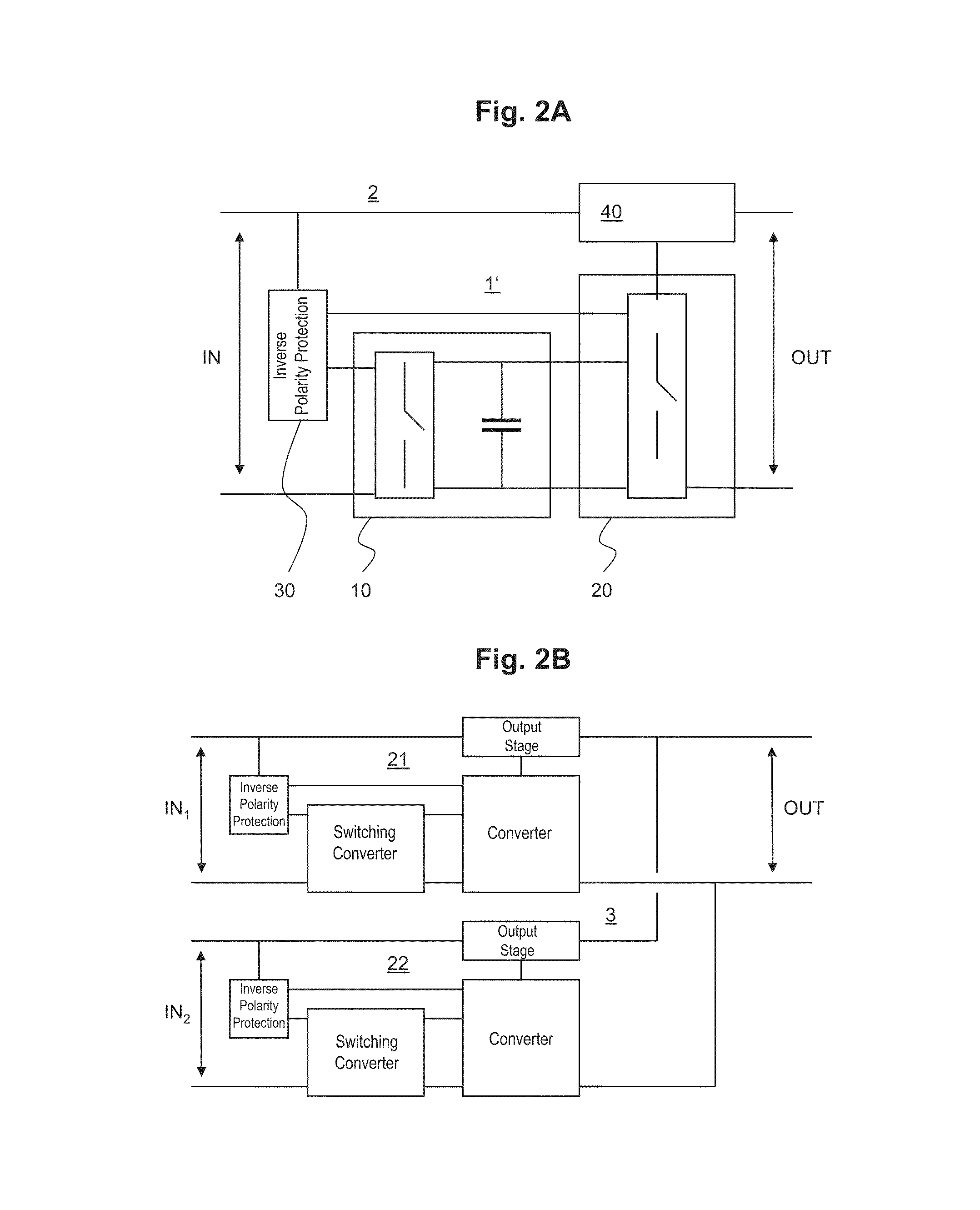
[0030]FIG. 2A shows a redundancy module 2 in accordance with the present invention. Here, the circuit arrangement in accordance with the present invention can be employed. It is an object in this regard to generate a voltage for the supply of semiconductor components or similar in a redundancy module. Here, the function of a module 2 can consist in the decoupling of feeding current supplies, which supply common loads or consumers.

[0031]More specifically, within the redundancy module 2 an output stage 40 is provided, which is connected between the supply voltage IN (Vin in FIGS. 1A and 1B) and the output OUT. Within the output stage 40, as an example of a decoupling element, a MOSFET 410 is employed, which, due to a corresponding controlling, has the same effect as a decoupling diode. The advantage of the MOSFET 410 is the possible reduction of conducting-state losses compared to a diode. If required, the effective conductive-state resistant can further be reduced by a parallel conne...


PUM


Abstract

A circuit arrangement for providing an output voltage and / or an output current from an input voltage Vin, comprising: a first switching converter (10) having a storage element (120) and a first switching element (110), adapted to charge the storage element (120) from the input voltage Vin up to a threshold voltage and a second switching converter (20) having a second switching element (210) adapted to start with the threshold voltage at the storage element (120) and to provide the output voltage Vout and / or the output current Iout from the input voltage Vin, wherein the first switching element (110) has a minimum driving voltage, at and above which the first switching element (110) can perform switching operations, the second switching element (210) has a minimum driving voltage, at and above which the second switching element (210) can perform switching operations, and wherein the minimum driving voltage of the first switching element is smaller than the minimum driving voltage of the second switching element.

Description

[0001]This application claims benefit of Serial No. DE 10 2010 028 149.2, filed 23 Apr. 2010 in Germany and which application is incorporated herein by reference. To the extent appropriate, a claim of priority is made to the above disclosed application.BACKGROUND OF THE INVENTION[0002]The invention pertains to a circuit arrangement for providing a stable output voltage and / or output current from an input voltage which is variable over a wide range and might also assume exceptionally low values from case to case, and as a possible application of such circuit, a redundancy module having active decoupling components.[0003]In systems and automation engineering, as well as in other fields of electronics, one usually employs internal supply voltages of about 3V to about 60V. Internal supply voltages are those voltages which are required by the electrical consumers which are connected to the internal supply network of the respective apparatus or the respective system, for their proper func...

Claims


Application Information

Patent Timeline
IPC IPC(8): H02M3/156H02J1/10H02M3/158H02M1/32H02M1/36H02M1/00
CPCH02M3/158H02M1/32H02M1/36H02M2001/007H02M1/007
Inventor BLAU, STEFFEN
Owner PULS GMBH
Why Eureka
Try Eureka