Pressure actuated film riding seals for turbo machinery

a technology of film riding seals and turbo machines, which is applied in the direction of engine seals, mechanical devices, engine components, etc., can solve the problems of poor efficiency of turbo-machineries, affecting efficiency, and leaked fluids failing to perform useful work, so as to reduce the axial momentum of flow

Active Publication Date: 2015-08-25
GENERAL ELECTRIC CO
View PDF44 Cites 37 Cited by
  • Summary
  • Abstract
  • Description
  • Claims
  • Application Information

AI Technical Summary

Benefits of technology

[0008]In accordance with an embodiment of the invention, a seal assembly for a rotary machine is provided. The seal assembly includes multiple sealing device segments disposed circumferentially intermediate to a stationary housing and a rotor. Each of the sealing device segments includes a stator interface element. The sealing device segment also includes a shoe plate comprising one or more labyrinth teeth facing the rotor and a load bearing surface region, wherein the shoe plate is configured to allow a high pressure fluid to an upstream portion of forwardmost labyrinth tooth and a low pressure fluid to a downstream portion of the aftmost labyrinth tooth and further configured to generate an aerodynamic force between the shoe plate and the rotor. The sealing device segment further includes a secondary seal configured to be in contact with the stator interface element at a radially outer end and configured to be in contact with an elevated nose of the shoe plate on a radially inner end; and multiple flexible elements attached to the shoe plate and to the stator interface element. The seal assembly further includes the rotor having a stepped section towards a high pressure side of the rotary machine for reducing an axial momentum of flow of fluid across the one or more labyrinth teeth of the shoe plate.

Problems solved by technology

Leakage of fluid through these gaps from regions of high pressure to regions of low pressure may result in poor efficiency for the turbo-machinery.
Such leakage may impact efficiency in that the leaked fluids fail to perform useful work.
The sealing systems, however, often are subject to relatively high temperatures, thermal gradients, and thermal and mechanical expansion and contraction during various operational stages that may increase or decrease the clearance therethrough.
For example, traditional labyrinth seals that are assembled to run very tight clearance during start-up transient phase might run with large clearances during steady state operations, thereby leading to poor performance at steady state operation.

Method used


Image

  • Pressure actuated film riding seals for turbo machinery
  • Pressure actuated film riding seals for turbo machinery
  • Pressure actuated film riding seals for turbo machinery

Examples


Embodiment Construction

[0037]When introducing elements of various embodiments of the present invention, the articles “a,”“an,”“the,” and “said” are intended to mean that there are one or more of the elements. The terms “comprising,”“including,” and “having” are intended to be inclusive and mean that there may be additional elements other than the listed elements. Any examples of operating parameters are not exclusive of other parameters of the disclosed embodiments.

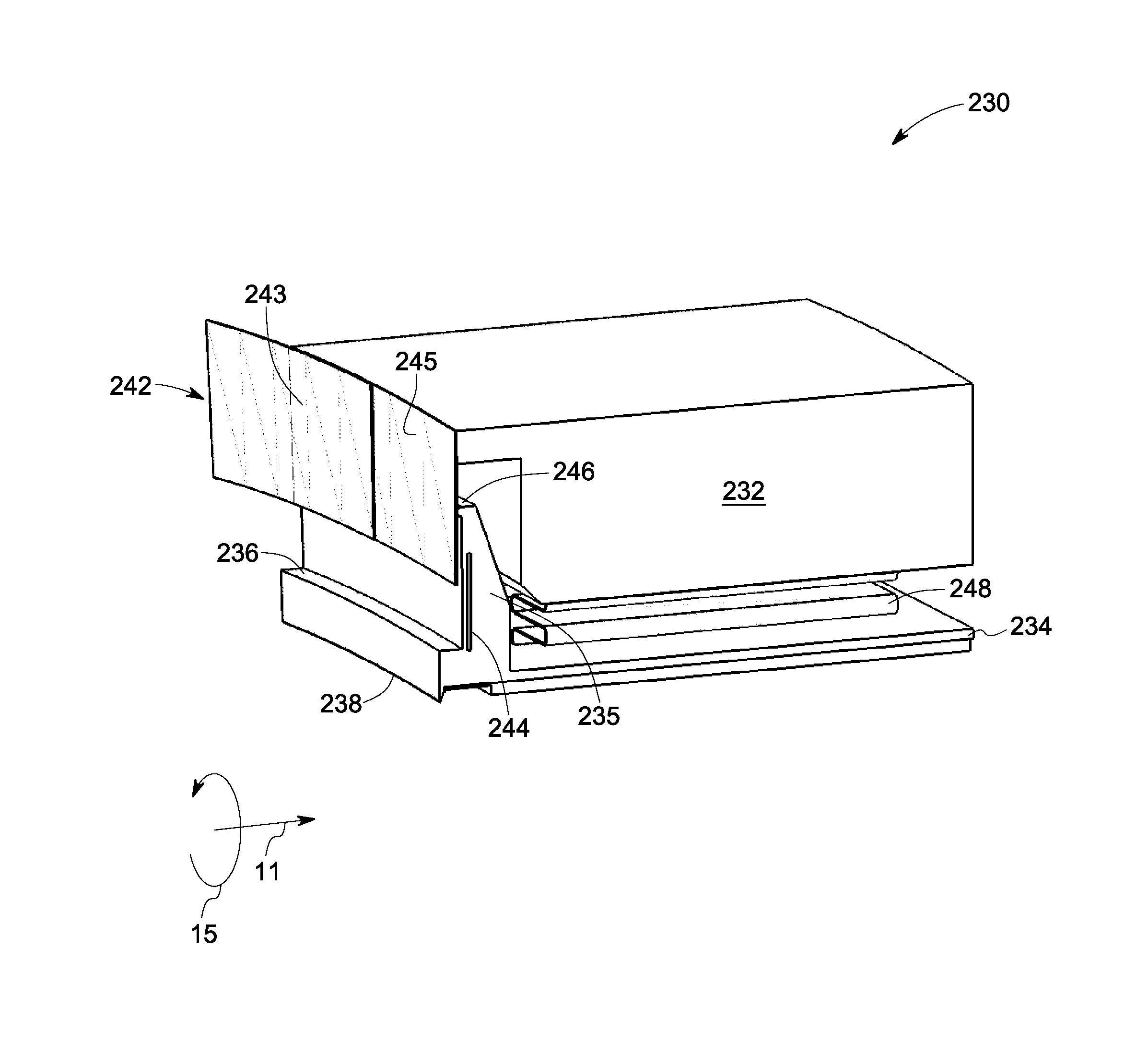
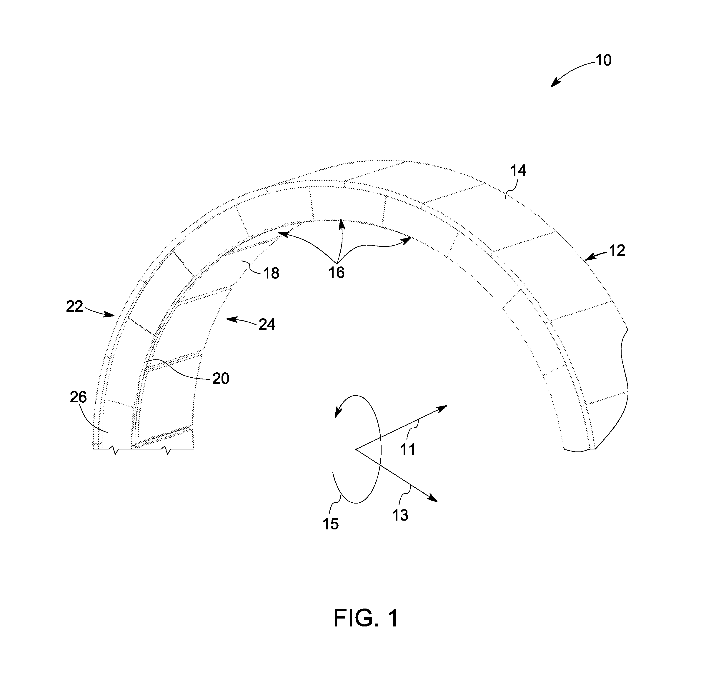
[0038]FIG. 1 is a perspective view of a film riding seal assembly 10 (only a few segments are shown instead of the entire 360 degree assembly) for a rotary machine in accordance with an embodiment of the present invention. The film riding seal assembly 10 is shown to have an orientation in axial, radial and circumferential direction as given by 11, 13 and 15 respectively. The seal assembly 10 is circumferentially arranged around a rotor shaft (not shown) that is axially located in the rotary machine such that the seal assembly 10 is intermediat...


PUM

PropertyMeasurementUnit
thicknessaaaaaaaaaa
flexibleaaaaaaaaaa
pressureaaaaaaaaaa

Abstract

A seal assembly for a rotary machine is provided. The seal assembly includes multiple sealing device segments disposed circumferentially intermediate to a stationary housing and a rotor. Each of the sealing device segments includes a stator interface element, a shoe plate having an extended portion having one or more labyrinth teeth facing the rotor and a load bearing portion, wherein the shoe plate is configured to generate an aerodynamic force between the shoe plate and the rotor. The sealing device segment further includes a secondary seal configured to be in contact with the stator interface element at a radially outer end and configured to be in contact with an elevated nose section of the extended portion of the shoe plate on a radially inner end; and multiple flexible elements attached to the shoe plate and to the stator interface element.

Description

CROSS REFERENCE TO RELATED APPLICATIONS[0001]This application is a Continuation in Part application to U.S. patent application Ser. No. 13 / 665,431, entitled “FILM RIDING AERODYNAMIC SEALS FOR ROTARY MACHINES,” filed Oct. 31, 2012, which is herein incorporated by reference in its entirety.STATEMENT REGARDING FEDERALLY SPONSORED RESEARCH & DEVELOPMENT[0002]This invention was made with partial Government support under contract number DE-FC26-05NT42643 awarded by U.S. Department of Energy. The Government has certain rights in the invention.BACKGROUND[0003]The present application relates generally to seal assemblies for turbo-machinery and more particularly relates to film riding seal assemblies for sealing rotor-stator gaps and the like.[0004]Various types of turbo-machinery, such as gas turbine engines, aircraft engines and steam turbines are known and widely used for power generation, propulsion, and the like. The efficiency of the turbo-machinery depends in part upon the clearances b...

Claims


Application Information

Patent Timeline
Patent Type & Authority Patents(United States)
IPC IPC(8): F16J15/447F16J15/44
CPCF16J15/447F16J15/442Y10T29/49826
Inventor BIDKAR, RAHUL ANILTHATTE, AZAM MIHIRGIBSON, NATHAN EVAN MCCURDYGIAMETTA, ANDREW PAUL
Owner GENERAL ELECTRIC CO
Why Eureka
Try Eureka