Method for controlling in-plane uniformity of substrate processed by plasma-assisted process

a plasma-assisted process and substrate technology, applied in the direction of coatings, chemical vapor deposition coatings, electric discharge tubes, etc., can solve the problem of uneven thickness

Active Publication Date: 2015-09-01
ASM IP HLDG BV
View PDF6 Cites 376 Cited by
  • Summary
  • Abstract
  • Description
  • Claims
  • Application Information

AI Technical Summary

Benefits of technology

[0006]To solve the above problems, in some embodiments, a deposition rate or etching rate of a film formed on a substrate in an area near the outer periphery of the substrate is controlled by increasing the flow rate of seal gas which is a gas jetting from a port provided at a location below the substrate and / or nearly flush with the substrate in a vicinity of the outer periphery of the substrate. In this disclosure, a gas which is used for controlling partial pressure and / or flux of gas near the outer circumference of a substrate and which is not used for processing the substrate (since this gas does not reach a central area and an inner area around the central area of the substrate surface) may be referred to as a “secondary gas”. By doing the above, partial pressure and flux of gas near the outer periphery of a substrate can effectively be controlled. In some embodiments, in addition to a showerhead for supplying a main process gas, at least one separate port for supplying a secondary gas is provided in a reaction chamber. Multiple ports (e.g., 3 to 30, preferably 10 to 20) for supplying a secondary gas can be provided along a circumferential direction of a substrate and / or along a vertical direction, thereby controlling in-plane uniformity of the substrate more precisely.
[0007]In some embodiments, by narrowing a clearance between the inner periphery of a separation ring which is provided around a susceptor and divides a reaction chamber and a transfer chamber, and the outer periphery of the susceptor, partial pressure or flux of gas in a vicinity of the outer periphery of the substrate can be controlled as effectively as when a separate port for supplying a secondary gas is provided in a bottom area of the reaction chamber or in an area of the reaction chamber flush with the substrate in a vicinity of the outer periphery of the substrate. By changing the clearance between the inner periphery of the separation ring and the outer periphery of the susceptor or changing the arrangement of the separate ports for circumferentially changing the supply quantity of secondary gas along the outer periphery of the substrate, more precise control over in-plane uniformity of the substrate can be achieved. For example, as viewed from above, a clearance between the inner periphery of the separation ring and the outer periphery of the susceptor can be set to be narrower in a portion of the clearance defined between a twelve o'clock direction and a three o'clock direction, and / or set to be wider in a portion of the clearance defined between a six o'clock direction and a nine o'clock direction, relative to the other portions of the clearance, so that the effect of the secondary gas can be enhanced in an area near the outer periphery of the substrate defined between a twelve o'clock direction and a three o'clock direction, thereby controlling in-plane uniformity of the substrate more directionally and precisely. In the above, the clearance can be divided in smaller sections than quadrants such as a section defined between a twelve o'clock direction and a one or two o'clock direction.

Problems solved by technology

Although the reasons for such in-plane unevenness of thickness of a film are unknown, the present inventors expect that unevenness of thickness may be caused by uneven adsorption of a material over a substrate surface due to uneven distributions of plasma and / or uneven activation on the substrate surface, or insufficient purge around the outer periphery of the substrate.

Method used


Image

  • Method for controlling in-plane uniformity of substrate processed by plasma-assisted process
  • Method for controlling in-plane uniformity of substrate processed by plasma-assisted process
  • Method for controlling in-plane uniformity of substrate processed by plasma-assisted process

Examples


reference example 1

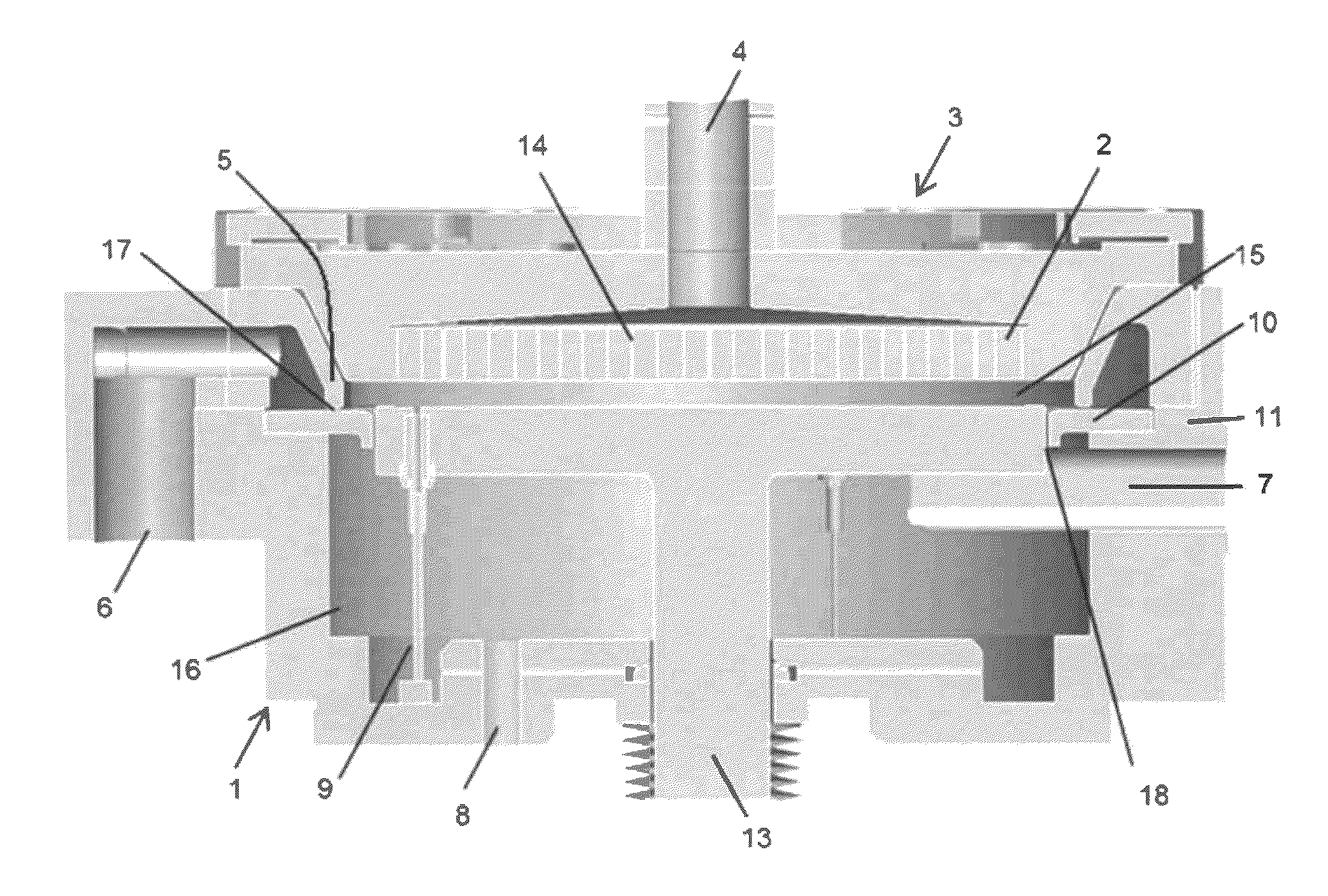
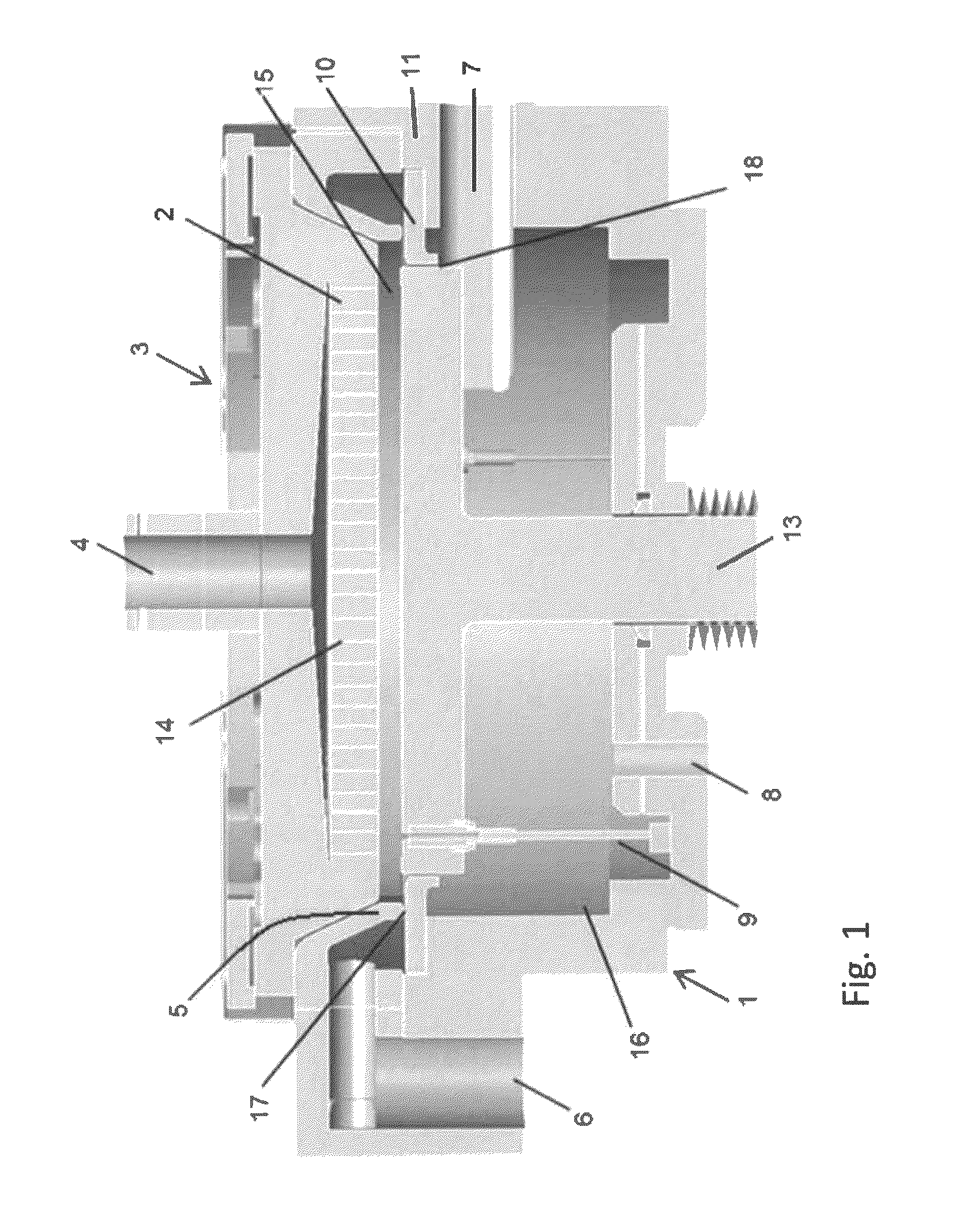
[0055]A plasma-enhanced ALD apparatus shown in FIG. 1 was used as a reactor to deposit a film on a substrate under the conditions shown in Table 1 below.

[0056]

TABLE 1Deposition stepElectrodes' gap [mm]7.5Pressure [Pa]400Tem. [° C.]300PrecursorBDEAS (bis(diethylamino)silane)Supply time [sec]0.2ReactantO2Gas flow [sccm]4,000 (continuous)Rare gasArGas flow [sccm]4,000 (continuous)RF power [W]See FIG. 9RF frequency [MHz]13.56Apply time [sec]See FIG. 9Purge [sec]0.3 between Precursor and RF powerSecondary gas supplySecondary gasHeGas flow [slm]0.2Clearance [mm]0.8 mm all around

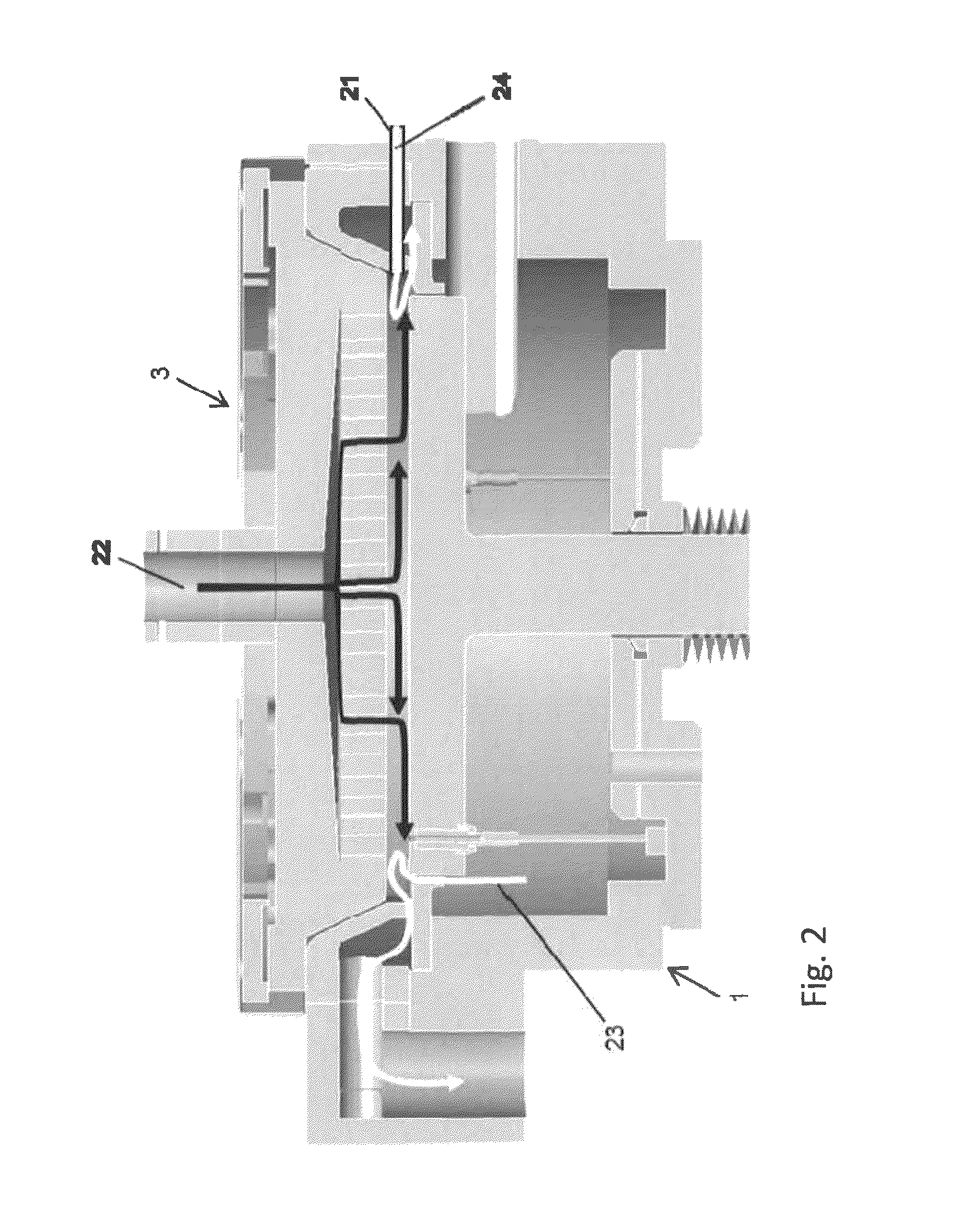
[0057]In this example, since the secondary gas flow was not substantial and only for sealing the transfer chamber, no inward flow of the secondary gas after entering the reaction space was expected. Further, the clearance between the susceptor and the separation ring was not narrow enough to increase flux of the secondary gas. The results are shown in FIG. 9. FIG. 9 shows images of thin-film thickness profile measu...

reference example 2

[0058]Films were deposited under the conditions which were the same as in Reference Example 1 except for the following shown in Table 2.

[0059]

TABLE 2RF Power (W)50200500800RF0.2convexconvex convexflatTime0.5convexconvexflatconcave(sec)1flatflatconcave concave

[0060]As can be seen from Table 2, as shown in Reference Example 1, when higher and longer RF power was applied, the film surface became concave wherein the thickness of the film in an area around the outer periphery of the substrate became greater than that of the film in middle and center areas.

example 1

[0061]Films were deposited under conditions similar to those in Reference Example 1 as shown in Table 3.

[0062]

TABLE 3Deposition step (PEALD)Electrodes' gap [mm]7.5Pressure [Pa]400Tem. [° C.]300PrecursorBDEASSupply time [sec]0.2ReactantO2Gas flow [sccm]3,000 (continuous)Rare gasArGas flow [sccm]8,000 (continuous)RF power [W]500RF frequency [MHz]13.56Apply time [sec]1.0Purge [sec]0.3 between Precursor and RF powerSecondary gas supplySecondary gasHeGas flow [slm]See FIG. 10Clearance [mm]0.8 (all around)

[0063]In this example, the flow rate of the secondary gas was changed, and as a result, surprisingly, the 3σ in-plane uniformity of thickness of the film was significantly improved as shown in FIG. 10 by increasing the flow of the secondary gas. FIG. 10 shows the relationship between in-plane uniformity of deposition and flow rate of control gas, with images of thin-film thickness profile measurement by 2D color map analysis of the deposited films. As can be seen from FIG. 10, the in-pla...


PUM

PropertyMeasurementUnit
diameteraaaaaaaaaa
diameteraaaaaaaaaa
inner diameteraaaaaaaaaa

Abstract

A method for controlling in-plane uniformity of a substrate processed by plasma-assisted process in a reactor, includes: supplying a principal gas to a reaction space, and discharging radially the principal gas from the reaction space through an annular duct; and supplying an secondary gas to the reaction space from an area in close proximity to an outer periphery of a susceptor, outside an outer circumference of the substrate as viewed from above, so as to flow at least partially in an inward direction passing the outer circumference of the substrate, reversing the direction of the secondary gas to flow toward the annular duct in a vicinity of the outer circumference of the substrate, and discharging radially the secondary gas together with the principal gas from the reaction space through the annular duct.

Description

BACKGROUND OF THE INVENTION[0001]1. Field of the Invention[0002]The present invention generally relates to a method for processing a substrate by plasma-assisted process, such as plasma-assisted deposition and plasma-assisted etching, particularly to a method for controlling in-plane uniformity of a substrate subjected to such processing.[0003]2. Description of the Related Art[0004]In a plasma-enhanced atomic layer deposition (PEALD), RF power is an important parameter for controlling the quality of a film depositing by PEALD. In general, high RF power and prolonged duration of plasma exposure contribute to good quality of a film. However, according to the present inventors' experience, when RF power is high, an area of the film near the outer periphery has a thickness greater than that of other areas of the film, i.e., in-plane uniformity of thickness of a film is degraded. Although the reasons for such in-plane unevenness of thickness of a film are unknown, the present inventors e...

Claims


Application Information

Patent Timeline
Patent Type & Authority Patents(United States)
IPC IPC(8): C23C16/509H01J37/32C23C16/455C23C16/458
CPCH01J37/32449C23C16/4551C23C16/4585C23C16/5096H01J37/32431C23C16/45519C23C16/45536
Inventor NAKANO, RYUINOUE, NAOKI
Owner ASM IP HLDG BV
Why Eureka
Try Eureka