Well centralizer

a centralizer and well technology, applied in the field of bow-type centralizers, can solve the problems of damage to the inner sealing profile, difficult to properly receive the casing within the wellhead, and affecting the sealing effect of the wellhead,

Active Publication Date: 2015-09-08
FRANKS INT
View PDF19 Cites 6 Cited by
  • Summary
  • Abstract
  • Description
  • Claims
  • Application Information

AI Technical Summary

Benefits of technology

[0018]Said bow spring assembly and said central tubular body member are beneficially rotatable relative to one another. In one preferred embodiment, the present invention includes a bow spring heel support journal to prevent such bow spring members from contacting the outer surface of said central tubular member when said bow springs are compressed, such as in a wellbore restriction, even when said central tubular body is rotated within said bow spring assembly. Further, said journal also provides a centralizer stop (that is, the stop ring portion of the end band prevents the centralizer from sliding off the central tubular member and allows it to be pulled in rather than pushed into a restriction).
[0019]Said bow spring heel support effectively eliminates contact between inwardly-compressed bow spring members and the outer surface of the central tubular member (particularly near the heels of the bow springs), as well as any torque forces and / or frictional resistance that said centralizer bow springs may create as the central tubular member rotates relative to said bow spring members and end bands. Put another way, when said bow spring members are fully elongated (such as when collapsed inward), said heel supports prevent said bow spring members from contacting the outer surface of said central tubular member.
[0021]In order to reduce and / or prevent damage to wellheads and, more particularly, polished surfaces of such wellheads, components of the present material can be comprised of synthetic or composite materials (that is, non-abrasive and / or low friction materials) that will not damage, gouge or mar polished surfaces of wellheads or other equipment. In most cases, such components include bow spring members, because such bow spring members extend radially outward the greatest distance (that is, exhibit the greatest outer diameter) relative to the central body of the centralizer, and would likely have the most contact with such polished surfaces.
[0024]In addition, the present invention includes an optional protective bolster assembly. The bolster assembly of the present invention can be used to protect the centralizer of present invention, and particularly the bow spring members thereof, from damage during transportation and / or handling of said centralizer assembly. In the preferred embodiment, the protective bolster assembly of the present invention is inexpensive, reusable and easy to install and remove. Further, said bolster assembly of the present invention can be beneficially constructed from composite material(s) to resist moisture absorption and prevent corrosion when in contact with metal components of a bow spring assembly or central tubular member. Additionally, such bolster assembly of the present invention can be beneficially collapsible for convenient storage and shipping of such bolster assembly when not in use or installed on a centralizer or other tool.
[0026]In an alternative embodiment, the bolster assembly of the present invention has rigid end pieces which can be molded or otherwise fabricated. This embodiment of the bolster assembly of the present invention, which can be utilized instead of conventional wooden crates or other similar devices commonly used for during the transportation and handling of such equipment, eliminates the need for securing bolster members in such crates.

Problems solved by technology

The running of pipe (drill string, casing and / or other equipment) through a wellhead can cause wear on the internal surface of a wellhead, thereby damaging the inner sealing profile of said wellhead and making it difficult for casing to be properly received within said wellhead.
This is especially true for items having a larger outer diameter than other pipe or tubular goods passing through a wellhead (such as, for example centralizers), as such larger items have a tendency to gouge, mar, scar and / or scratch polished surfaces or sealing areas of said wellhead.
Conventional rotating centralizer designs cause high rotating torques due to such frictional resistance forces encountered during pipe rotation operations.

Method used


Image

  • Well centralizer
  • Well centralizer
  • Well centralizer

Examples


Embodiment Construction

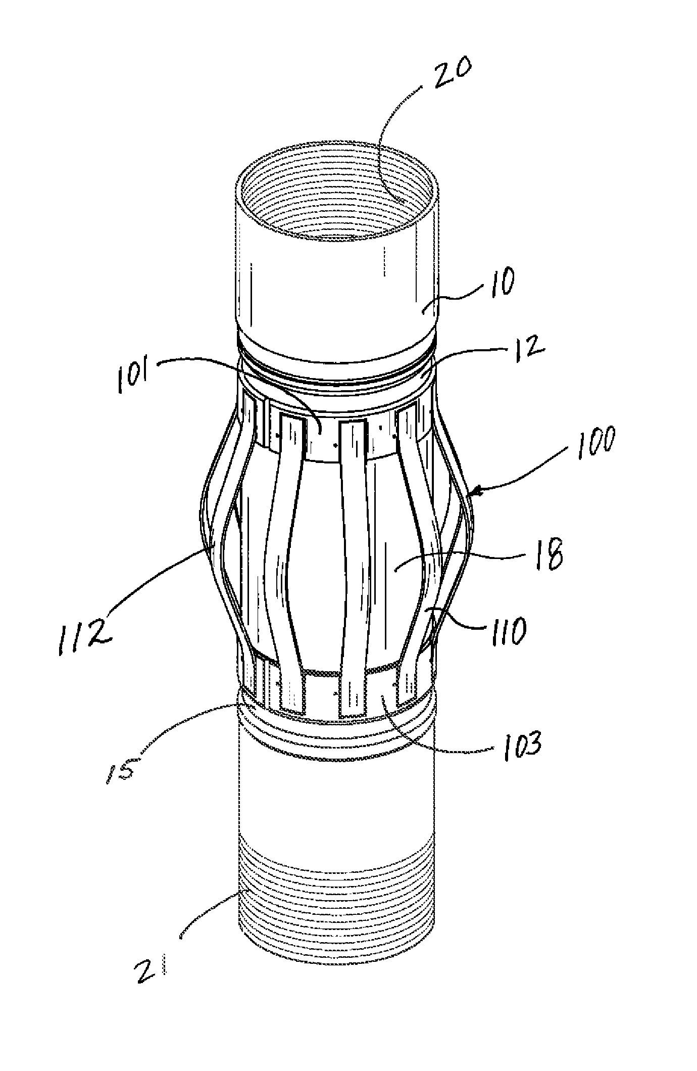
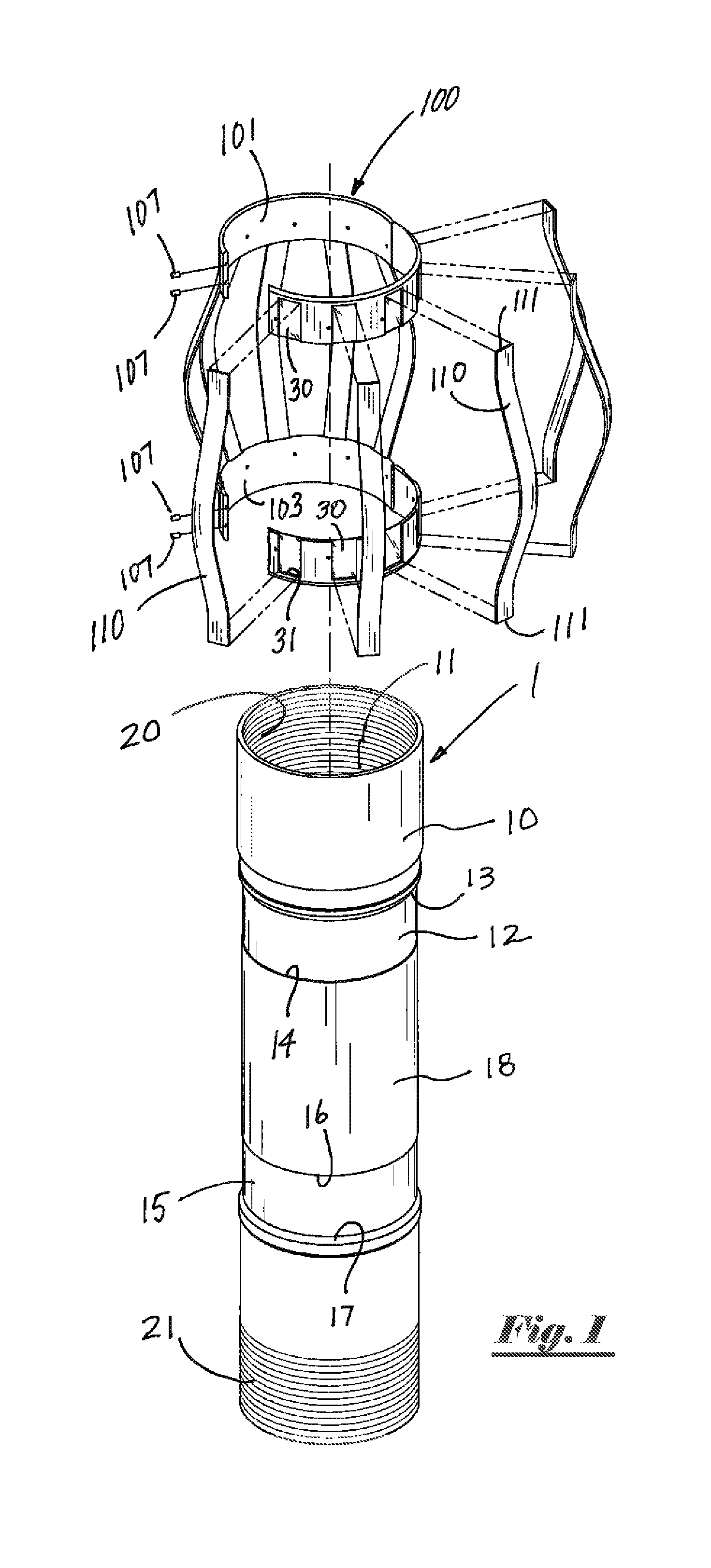
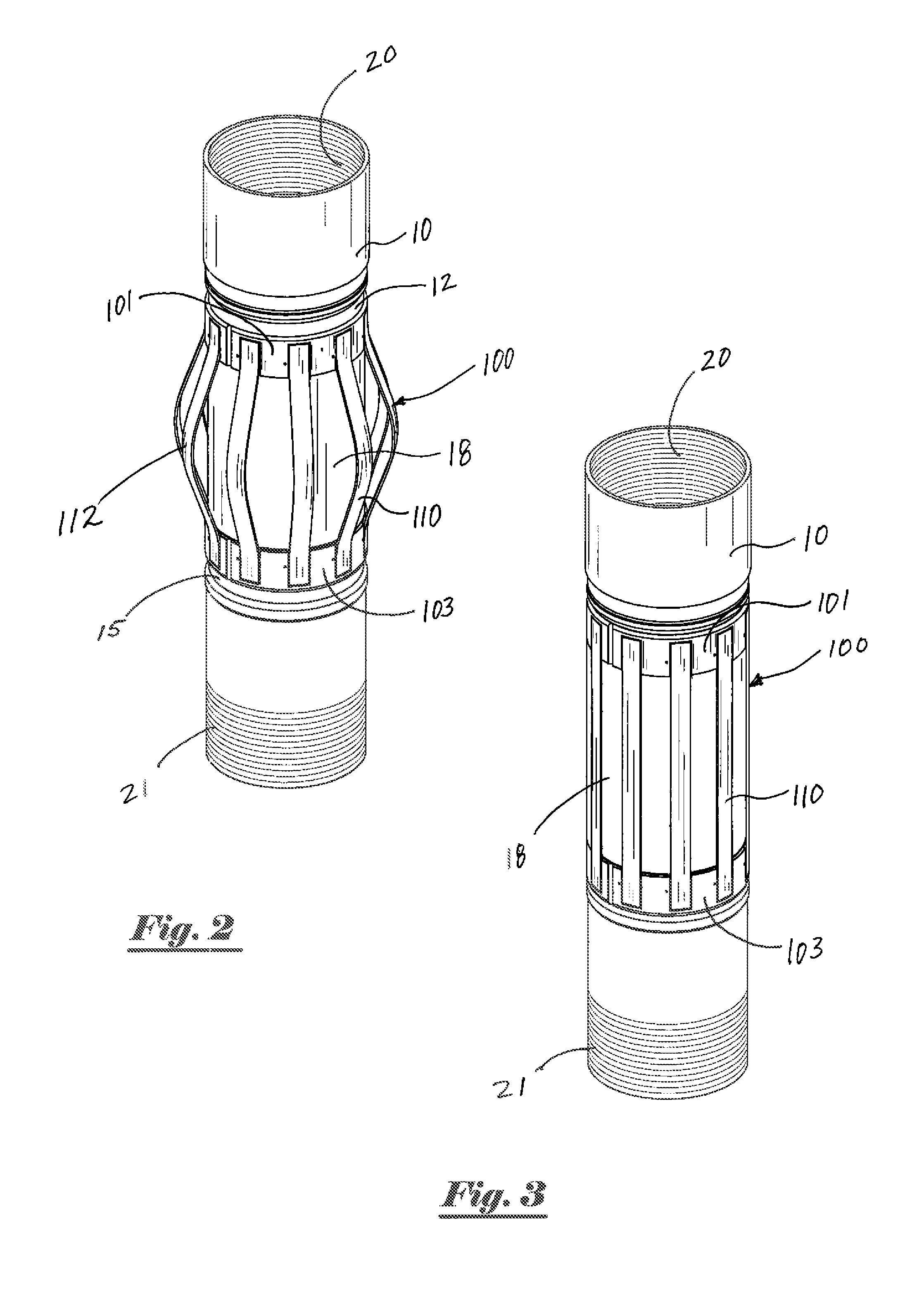
[0049]Referring to the drawings, FIG. 1 depicts a partially exploded perspective view of a centralizer assembly 1 of the present invention. Centralizer assembly 1 of the present invention generally comprises a central tubular body member 10 having a central flow bore 11 extending therethrough. Upper channel 12 and lower channel 15 each extend around the external surface of said central tubular body member 10. Said upper channel 12 and lower channel 15 are oriented substantially parallel to each other, substantially perpendicular to the longitudinal axis of central flow bore 11 of said tubular body member 10, and substantially around the entire outer circumference of said tubular body member 10.

[0050]Central body member 10 has upper threaded connection 20 and lower threaded connection 21. In the preferred embodiment, said lower threaded connection 21 is a male pin-end threaded connection, while upper threaded connection 20 is a female box-end threaded connection; said connections 20 ...


PUM

PropertyMeasurementUnit
frictionaaaaaaaaaa
lengthaaaaaaaaaa
depthaaaaaaaaaa

Abstract

A centralizer assembly having a tubular body member with upper and lower channels extending around the external surface of said central tubular body member. A bow spring assembly having bow spring members is installed around the outer surface of the tubular body member and can rotate about the outer surface of the central tubular body member. Bow spring heel supports prevent the bow spring members from contacting the outer surface of the central tubular member when compressed. Non-abrasive materials prevent damage to wellhead or other polished bore receptacles. A robust bolster frame protects the centralizer assembly during shipping, storage or other periods of non-use.

Description

BACKGROUND OF THE INVENTION[0001]1. Field of the Invention[0002]The present invention pertains to bow-type centralizers used during operations in oil and / or gas wells. More particularly, the present invention pertains to bow-type centralizers used on casing strings or other tubular goods run into said wells.[0003]2. Brief Description of the Prior Art[0004]Drilling of an oil or gas well is frequently accomplished using a surface drilling rig and tubular drill pipe. When installing drill pipe (or other tubular goods) into a well, such pipe is typically inserted into a wellbore in a number of sections of roughly equal length commonly referred to as “joints”. As a well penetrates deeper into the earth, additional joints of pipe must be added to the ever lengthening “drill string” at the drilling rig in order to increase the depth of the well.[0005]After a well is drilled to a desired depth, relatively large diameter pipe known as casing is typically installed within a well and then ceme...

Claims


Application Information

Patent Timeline
Patent Type & Authority Patents(United States)
IPC IPC(8): E21B19/24E21B17/10
CPCE21B19/24E21B17/1028E21B17/1078Y10T29/49826
Inventor JORDAN, J. CHRISTOPHERMARTENS, JAMES G.ARCEMENT, JEFFREY J.MONDELLI, JUAN CARLOSHEBERT, JOHN E.SCOTT, SCOTTIE J.DUPRE', THOMAS A.
Owner FRANKS INT
Why Eureka
Try Eureka