High-flow electro-hydraulic actuator

a technology of electro-hydraulic actuators and actuators, which is applied in the direction of valve housings, valve operating means/release devices, transportation and packaging, etc., can solve the problems of vibration, position error of the actuator, and the inefficiency of the conventional servo-vacuum, etc., and achieve cost-effective effects

Active Publication Date: 2015-09-08
WOODWARD GOVERNOR CO
View PDF27 Cites 11 Cited by
  • Summary
  • Abstract
  • Description
  • Claims
  • Application Information

AI Technical Summary

Benefits of technology

[0008]In one aspect, embodiments of the invention provide a high-reliability, cost-effective servo-valve assembly that is not susceptible to failure caused by contaminated fluid. In particular embodiments, the rotary control valve may be actuated by a direct-coupled Limited Angle Torque (LAT) motor, a geared, brushless DC motor, or some other rotary electric actuating element with an integrated driver circuit.

Problems solved by technology

However, some conventional servo-valves do not operate very efficiently or can fail when regulating the flow of contaminated fluids.
Further, traditional servo-valves can be adversely affected by vibration.
Vibration in the axial direction of the spool can move it from the desired position causing a position error of the actuator.
Additionally, conventional servo-valves are typically non-compliant with Div. 1 / Zone 1 hazardous location (explosion-proof) requirements.
Typically, explosion-proof servo-valves are considered “specials” and are usually expensive devices requiring long lead times.
The need to maintain tight tolerances leads to time-consuming manufacturing processes and testing of the device, and drives up the cost of traditional servo-valves.
Also, in some cases, contamination in the fluid flow may restrict flow through nozzles in the first stage of the servo-valve.
In other cases, small diameter wire used for the torque motor winding is subject to strain failure and is another source of poor reliability.
If the filter supplying the first stage element plugs, or pressure is lost for some other reason, there is a risk that the servo-valve will not easily move to the failsafe position.
In some cases, conventional direct drive or proportional valves (rotary or linear) often have a “wet” drive motor that can collect iron particles from the oil, which can eventually decrease the performance of the valve.
Further, conventional direct drive or proportional valves (rotary or linear) that have high flow capacity have high flow forces acting on the moving element.
This requires a high-force electrically powered first stage that can have high power requirements and / or be too slow for good dynamic control.
Also, conventional direct drive or proportional valves often only have a single control signal input and a single power input.
Failure of either input causes the servo-valve to no longer function.

Method used


Image

  • High-flow electro-hydraulic actuator
  • High-flow electro-hydraulic actuator
  • High-flow electro-hydraulic actuator

Examples


Embodiment Construction

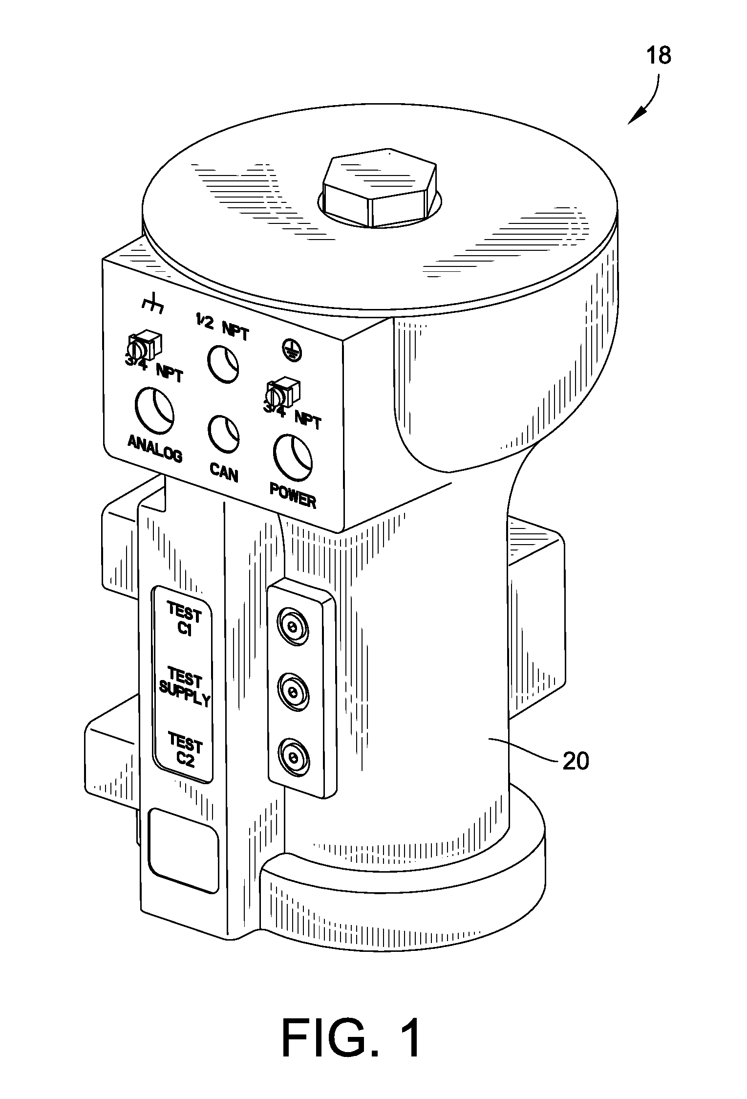
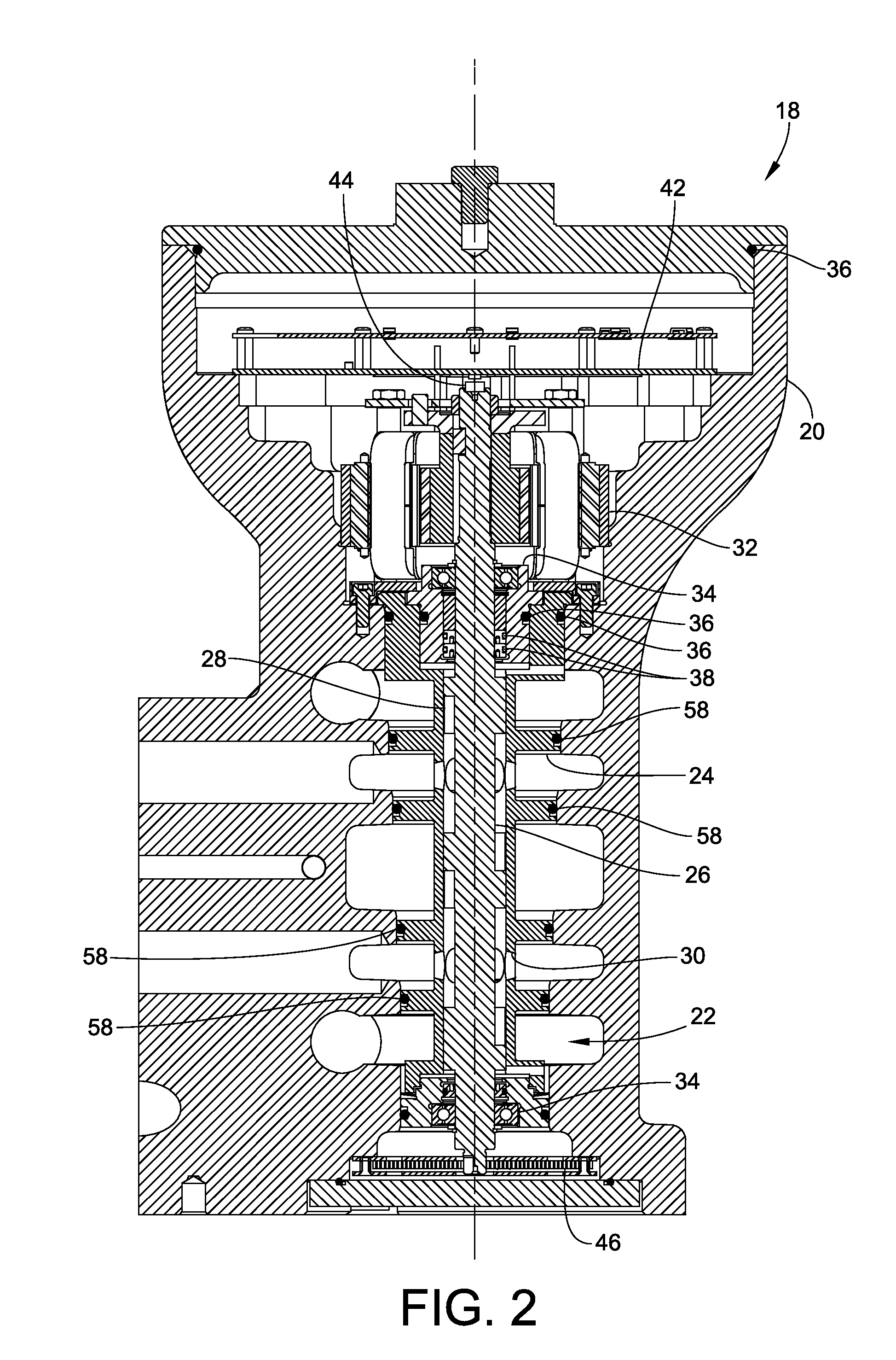
[0035]FIG. 1 is a perspective view of a servo-valve assembly with integrated electrical actuator 18, constructed in accordance with an embodiment of the invention. The assembly includes a housing 20 with a rotary control valve 22 (See FIG. 2) positioned therein and operable to selectively direct fluid flow into and out of various ports of the assembly. The housing 18 (as well as various internal components thereof) is a Div. 1 / Zone 1 rated, IP 56 enclosure. As will be explained in greater detail below, the assembly overcomes existing problems in the art by providing a highly reliable, high flow, low actuation force flow control device that is pressure insensitive and vibration and contaminant resistant. The actuator 18 dislcosed herein may be employed in the context of trip valves, relief valves, reducing valves, as well as in the context of the control of hydraulic fluid, e.g. on / off control, flow modulation, directional control, pressure control, etc.

[0036]Turning now to FIG. 2, e...


PUM


Abstract

Embodiments of the invention provide a high-reliability, cost-effective electro-hydraulic servo-valve assembly that is not susceptible to failure caused by contaminated fluid. In particular embodiments, the electro-hydraulic servo-valve assembly includes a rotary valve that may be actuated by either a direct-coupled Limited Angle Torque (LAT) motor, a geared, brushless DC motor, or some other rotary electric actuating element with an integrated driver circuit. In particular embodiments, the rotary valve element made up of an outer sleeve element and an inner spool element, with matching ports and slots, respectively.

Description

CROSS-REFERENCE TO RELATED PATENT APPLICATIONS[0001]This patent application claims the benefit of U.S. Provisional Patent Application No. 61 / 532,922, filed Sep. 9, 2011, the entire teachings and disclosure of which are incorporated herein by reference thereto.FIELD OF THE INVENTION[0002]This invention generally relates to electro-hydraulic actuators or servo-valves.BACKGROUND OF THE INVENTION[0003]Electro-hydraulic servo-valves are widely used to control the flow of hydraulic fluid into and out of power cylinders that are used to control, for example, the flow or pressure of fuel, air, or steam. However, some conventional servo-valves do not operate very efficiently or can fail when regulating the flow of contaminated fluids. Further, traditional servo-valves can be adversely affected by vibration. Vibration in the axial direction of the spool can move it from the desired position causing a position error of the actuator. Additionally, conventional servo-valves are typically non-com...

Claims


Application Information

Patent Timeline
Patent Type & Authority Patents(United States)
IPC IPC(8): F16K31/02F15B13/044F15B13/04F16K11/076F16K31/04F16K27/04
CPCF15B13/0406F15B13/0444F16K11/076F16K27/041F16K27/048F16K31/041Y10T137/86863
Inventor GREEB, KEVIN E.LAFLEUR, PHILIP A.WORKMAN, JONATHAN P.BEEN, JOHN J.
Owner WOODWARD GOVERNOR CO
Why Eureka
Try Eureka