
Open-loop GPS antenna

a gps antenna and open loop technology, applied in the direction of antennas, elongated active element feeds, electrical devices, etc., can solve the problems of high production cost of patch antennas and inability to adapt to use horn antennas, and achieve the effects of low cost, light weight and small volum

Active Publication Date: 2015-09-08
ASKEY COMP
View PDF5 Cites 2 Cited by
  • Summary
  • Abstract
  • Description
  • Claims
  • Application Information

AI Technical Summary

Benefits of technology

The open-loop GPS antenna achieves a larger signal reception and transmission range, meets the slim and lightweight requirements of GPS devices, and provides flexibility in configuration while maintaining effective GPS functionality.

Problems solved by technology

However, each type of antenna also has its own relative drawbacks, for instance, the dipole antenna has a smaller gain and a narrower operational band, a field of the bow-tie antenna is much inconsistent when operating at each frequency, the horn antenna is not adapted to be used in a mobile communication and so forth.
Current GPS electronic device becomes more and more strict in terms of slim and light weight requirements, and since a weight and a size of the patch type antenna are more difficult to be reduced, it occupies a certain volume of the wireless electronic device, and as in terms of the slim and light weight requirements, this is no doubt a limitation.
Moreover, a production cost of the patch type antenna is also higher.

Method used


Image

  • Open-loop GPS antenna
  • Open-loop GPS antenna
  • Open-loop GPS antenna

Examples


Embodiment Construction

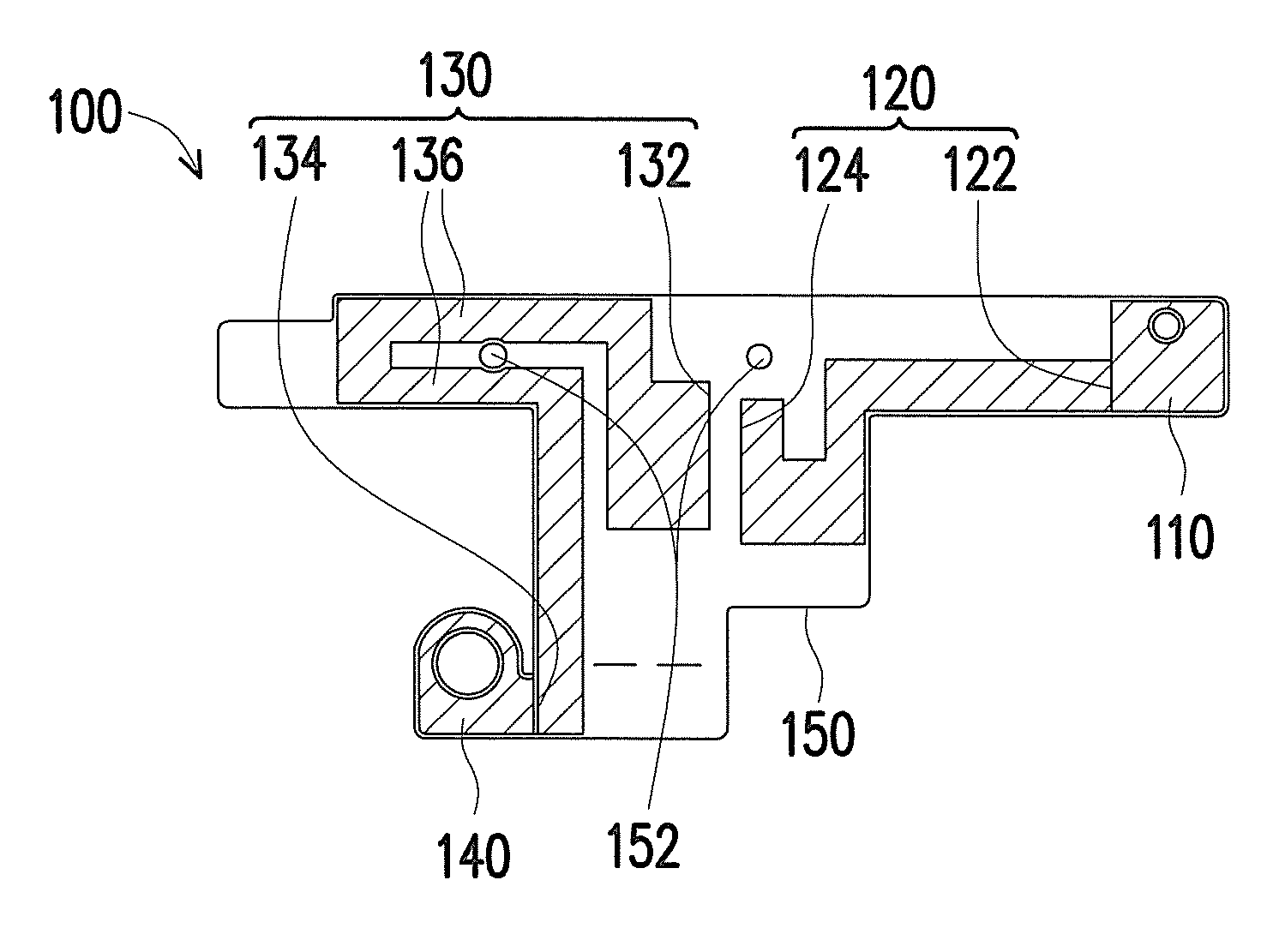
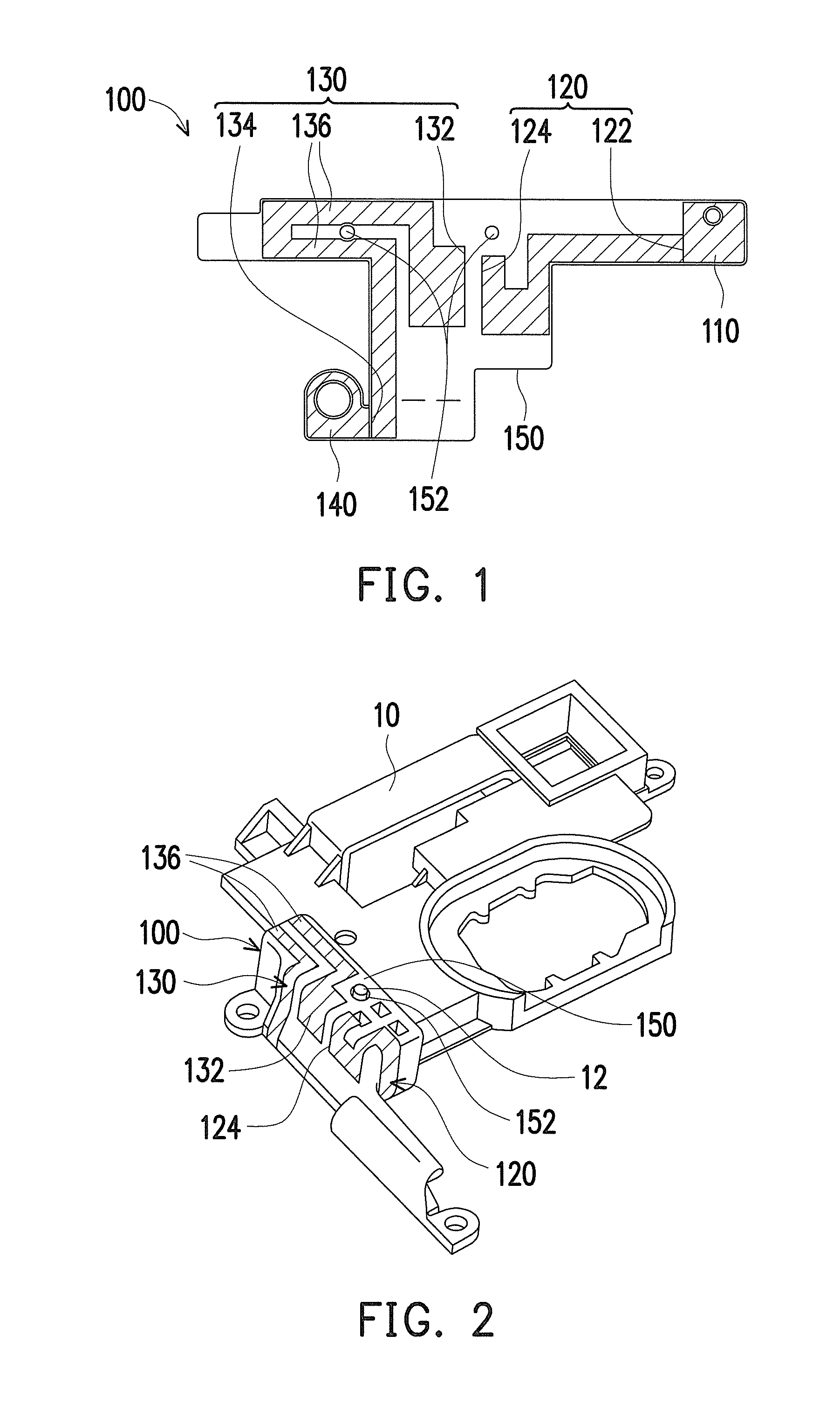
[0027]FIG. 1 is a schematic diagram illustrating an open-loop GPS antenna according to an embodiment of the invention. FIG. 2 is a schematic diagram illustrating the open-loop GPS antenna of FIG. 1 being configured on an insulation object. Referring to FIG. 1 and FIG. 2, the open-loop GPS antenna 100 of the present embodiment is adapted to be configured on an insulation object 10. In the present embodiment the insulation object 10 a plastic piece; in other embodiment, a material of the insulation object 10 may also be a ceramic or so forth; the type of the insulation object 10 is not limited thereto. The insulation object 10 may be a component in within a GPS electronic device (not shown), and since the open-loop GPS antenna 100 has a small volume and is bendable, the open-loop GPS antenna 100 may be directly adhered on the insulation object 10 according to a conformation of the insulation object 10 so as to receive and transmit a GPS signal; this part is to be described in detail b...


PUM


Abstract

An open-loop GPS antenna configured on an insulation object is provided. The open-loop GPS antenna includes a feed, a high frequency circuit, a low frequency circuit and a ground. The high frequency circuit includes a first end, connected to the feed, and a second end. The low frequency circuit includes a third end and a fourth end. The third end is disposed parallel to the second end so as to couple to the second end and generate a capacitance effect to transmit a signal. The fourth end is connected to the ground.

Description

CROSS-REFERENCE TO RELATED APPLICATION[0001]This application claims the priority benefit of Taiwan application serial no. 101143486, filed on Nov. 21, 2012. The entirety of the above-mentioned patent application is hereby incorporated by reference herein and made a part of this specification.BACKGROUND[0002]1. Field of the Invention[0003]The invention relates to a global positioning system (GPS) antenna, and more particularly, to an open-loop GPS antenna.[0004]2. Description of Related Art[0005]As technology advances, current general public communications have been gradually replaced by wireless communications, such as cell phone, personal digital assistant (PDA) with wireless Internet access, global positioning system (GPS) and so forth, which are all within the scope of the wireless communications; however, the wireless communications normally require the use of an antenna for transmitting signal.[0006]Frameworks of the antenna have different types, such as a dipole antenna, a bow...

Claims


Application Information

Patent Timeline
Patent Type & Authority Patents(United States)
IPC IPC(8): H01Q1/38H01Q7/00H01Q9/42
CPCH01Q1/38H01Q7/00H01Q9/42
Inventor LIU, CHIEN-SHENGCHAN, YU-CHIENLO, KUO-CHAOCHOU, TZU-HSUAN
Owner ASKEY COMP
Learn More