Electric damper

a damper and electric technology, applied in the field of electric dampers, can solve the problems of inability to recover or render useable energy drawn from the system, and the structure design of electric dampers known in the art is relatively complex

Active Publication Date: 2015-09-15
AUDI AG
View PDF15 Cites 3 Cited by
  • Summary
  • Abstract
  • Description
  • Claims
  • Application Information

AI Technical Summary

Benefits of technology

[0006]The invention is based on the problem to provide an electric damper which is improved, especially in terms of structural design.
[0008]The electric damper according to the invention is constructed in a particularly simple way and can easily be attached, for example, to a vehicle body of a motor vehicle. The operating principle of the electric damper is based on the coupling of a generator, comprised of a stationary stator and a rotor rotatable in relation thereto, with a gear mechanism, with the output member of the gear mechanism in the form of the second gear element transmitting a rotational movement, introduced directly by the lifting element which is coupled with the first gear element operating as drive element, onto the rotor. The rotational movement introduced into the rotor via the second gear element provides the damping via the generator and the recovery or conversion of the mechanical damping energy, originally resulting from the mass movement, to the current produced on the generator side.
[0013]The rotor has advantageously a cylindrical base shape. The shape of the rotor tracks substantially the shape of the generator housing, thereby promoting the mentioned especially compact structure of the generator and also of the electric damper overall. The rotor may in exceptional cases also have different shapes that are appropriate for installation in the housing.
[0019]As an alternative, the gear mechanism may also be a strain wave gearing with a ring-shaped or cylinder-shaped flexible unit having an external toothing, a rigid unit forming the first gear element and having an internal toothing in mesh with the external toothing of the flexible unit, and an oval rotary element which is arranged inside the flexible unit and interacts with the flexible unit such as to deform it and which is dynamically coupled with the rotor and forms the second gear element. Strain wave gearings or harmonic drive gearing are known to be characterized by high transmission ratios, high stiffness, compact configuration and slight play.
[0022]In the event of a strain wave gearing, a flexible rolling-contact bearing, in particular a roller bearing or needle bearing, is preferably arranged between the first and second gear elements. As a consequence, the oval rotary element is capable to roll off especially smoothly upon the flexible unit so that friction can be significantly reduced between the two gear elements.
[0024]Cycloid gearings also realize high transmission ratios so that even small angular rotations of the first gear element are transmitted at high ratio to the second gear element and further to the rotor. The second gear element is arranged preferably in midsection on a cam disk which is profiled on the outside in a waved manner and rotates within a fixed housing ring having corresponding counter teeth, but is radially movable therein. Coupled to the cam disk is further the first gear element, i.e. the ring-shaped or cylinder-shaped unit, which has respective coupling pins for engagement in diametrically greater bores of the cam disk so that the cam disk is able to execute radial movements when the first gear element is arranged with fixed rotation axis.

Problems solved by technology

However, they are not capable to recover or render useable energy drawn from the system during damping.
Electric dampers known in the art have, however, a relatively complex structural design.

Method used


Image

  • Electric damper
  • Electric damper
  • Electric damper

Examples


Embodiment Construction

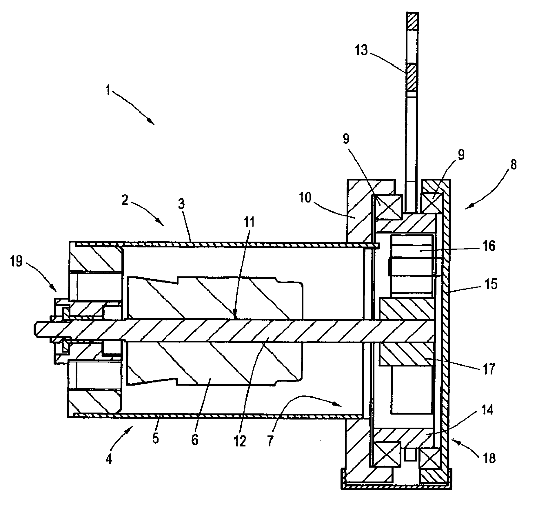
[0029]FIG. 1 shows a basic illustration of an electric damper 1 for damping a relative movement between first and second masses (both not shown) according to an exemplary embodiment of the invention. The damper 1 includes a generator 2 driven by the mass movement and having a fixed stator 5 integrated in an inner housing wall of a first housing portion 4 of a hollow-cylindrical housing 3, and a cylindrical rotor 6 rotatable in relation thereto. The housing 3 is connected via a second housing portion 7 to a gear mechanism 8 which is coupled with the generator 2 and configured by way of example as planetary gear train. As described above, other types of gear mechanisms are, of course, also conceivable within the scope of the invention, in addition to the configuration of the gear mechanism 8 as planetary gear train.

[0030]The housing 3 is, for example, non-rotatably arranged to a vehicle structure, optionally via the intervention of elastomeric bearings (not shown). The attachment to t...


PUM


Abstract

Electric damper for damping the relative movement between first and second masses, comprising a generator driven by the mass movement and having a fixed stator and a rotor rotatable relative thereto, and a gear mechanism coupled to the generator, wherein at least one first gear element, directly connected to a lifting member (13) that is movable by the mass movement, is caused to rotate by the mass movement, which first gear element is dynamically coupled by direct or indirect transmission at least one further gear element, with the second gear element being dynamically coupled to the rotor (6) of the generator (2) such that the rotor (6) is caused to rotate in relation to the stator (5).

Description

CROSS-REFERENCES TO RELATED APPLICATIONS[0001]This application is the U.S. National Stage of International Application No. PCT / EP2012 / 000113, filed Jan. 12, 2012, which designated the United States and has been published as International Publication No. WO 2012 / 100910 and which claims the priority of German Patent Application, Serial No. 10 2011 009 608.6, filed Jan. 27, 2011, pursuant to 35 U.S.C. 119(a)-(d).BACKGROUND OF THE INVENTION[0002]The invention relates to an electric damper for damping the relative movement between first and second masses, having a generator driven by the mass movement and including a fixed stator and a rotor rotatable relative thereto, and a gear mechanism coupled to the generator.[0003]Many areas of technology require a damping of relative movements between two components of a vibratory mechanical system. An example that is by no means limiting, involves vibration damping of a motor vehicle body in the area of the suspension of the body on the chassis. ...

Claims


Application Information

Patent Timeline
Patent Type & Authority Patents(United States)
IPC IPC(8): H02K7/06F16F15/03B60G17/08H02K7/116B60G13/14
CPCH02K7/116B60G13/14B60G17/08F16F15/035B60G2202/20B60G11/23B60G15/06B60G17/025B60G2202/1424B60G2202/22B60G2202/30B60G2202/42B60G2202/442B60G2204/4191
Inventor WILLEMS, MARCO
Owner AUDI AG
Why Eureka
Try Eureka