Versatile spin-polarized electron source

a technology of electron source and spin-polarized electron, which is applied in the field of photoelectron spin, can solve the problems of difficult and tedious production of gaas photocathodes, difficulty in polarizing devices, and the extreme vacuum of tediously prepared surfaces, and achieves high quality, high efficiency, and versatility.

Inactive Publication Date: 2015-09-22
THE UNITED STATES AS REPRESENTED BY THE DEPARTMENT OF ENERGY
View PDF2 Cites 4 Cited by
  • Summary
  • Abstract
  • Description
  • Claims
  • Application Information

AI Technical Summary

Benefits of technology

[0011]The ability to shine polarized light on a topological insulator and excite spin-polarization-tailored electrons has potential for the field of spintronics, electronics that exploit spin as well as charge. Devices that optically control electron distribution and flow would constitute a significant advance, allowing more versatile and efficient high-tech gadgets to be created. A more immediate utility of an easily controlled spin-polanized electron source is the application of a high quality photocathode source. This photocathode source could be available for many applications that require electron beams with specific spin polarization, as the embodiments of the present invention allow for spin-polarization of electrons to be precisely and conveniently controlled in three dimensions.

Problems solved by technology

This current method of GaAs photocathodes is imperfect.
The production of this layer is difficult and tedious.
This tediously prepared surface must be kept in extreme vacuum conditions and deteriorates within several days at 1×10⁻¹¹ torr.
Another issue with the layering for the GaAs photocathode method is that the spin-polarization is low.
These highly specialized wafers have been shown to yield 90% polarization; however, these are much more expensive, difficult to work with, and give inconsistent results.
A third issue with the layering of the GaAs photocathode method is that the resulting spin-polarization is locked along the axis of the laser beam.
Magnetic elements can also be introduced to further manipulate the spin orientation, but these electrostatic optics and magnetic elements all add up to further complications, added errors, and higher costs.

Method used


Image

  • Versatile spin-polarized electron source
  • Versatile spin-polarized electron source
  • Versatile spin-polarized electron source

Examples


Embodiment Construction

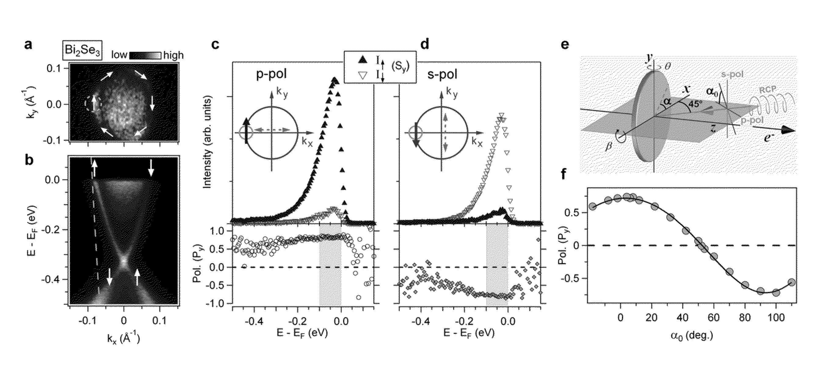
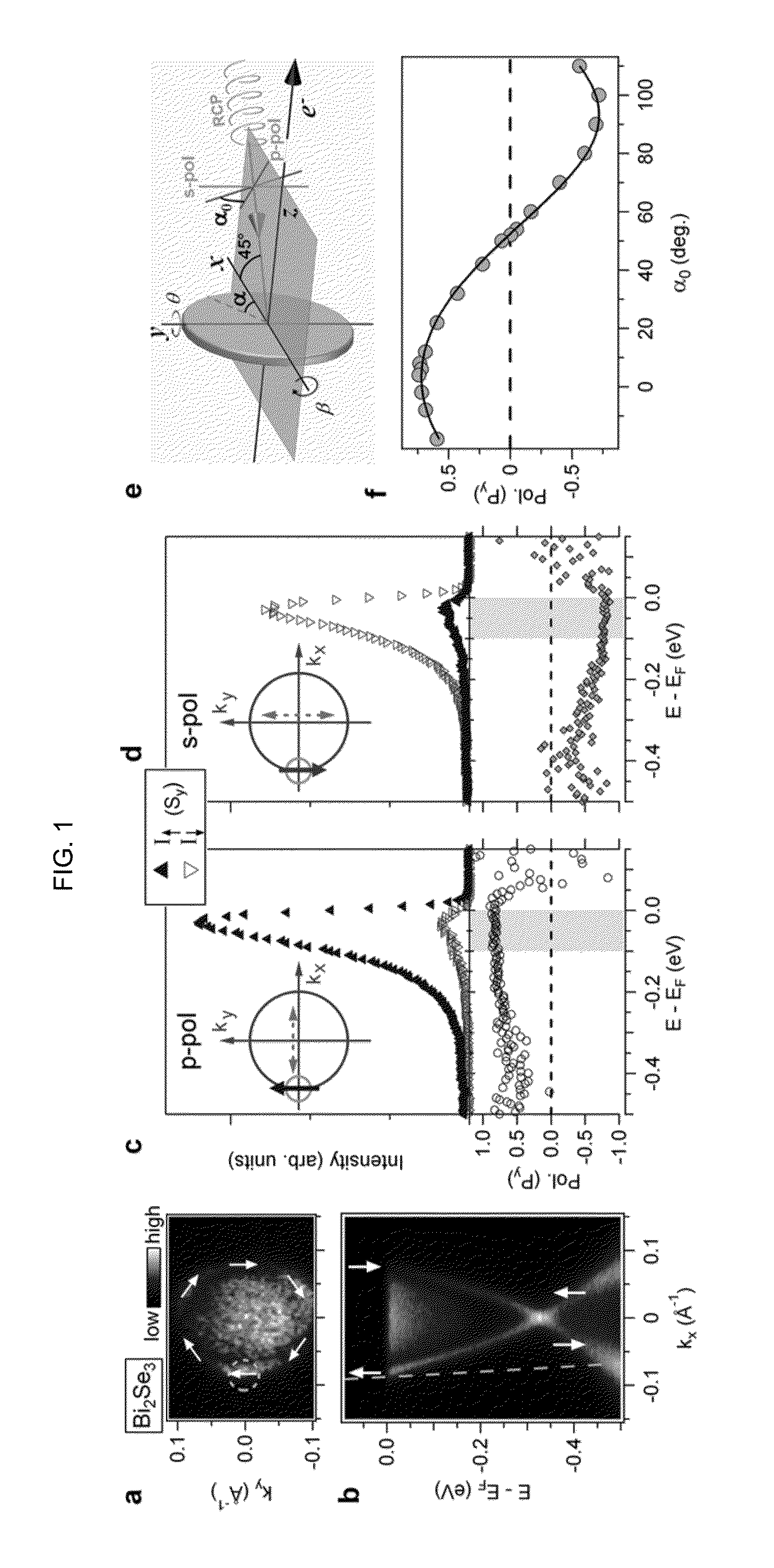
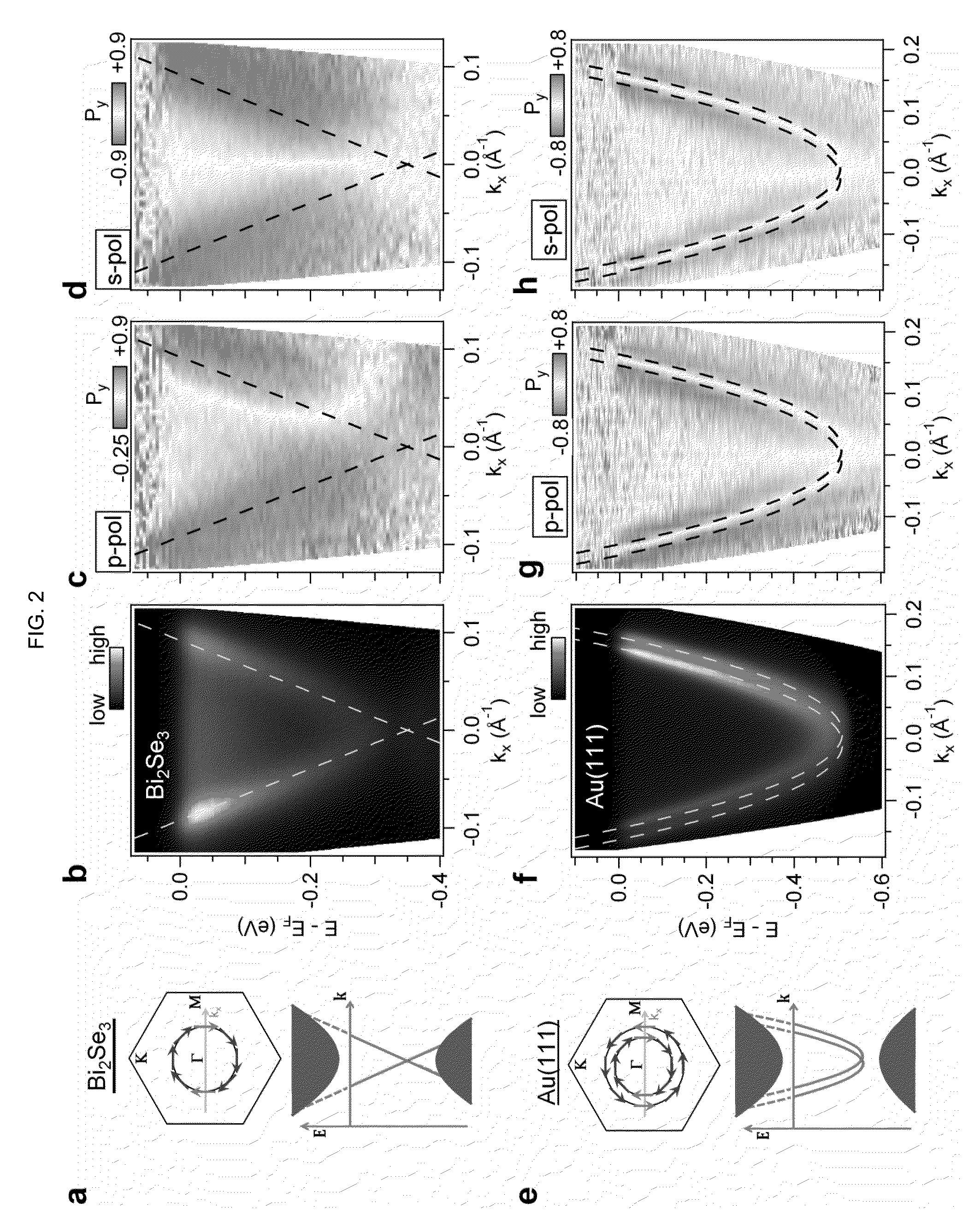
[0021]One or more embodiments relates to controllable spin-polarized electron sources and methods for creating controllable spin-polarized electron sources. More specifically, one or more embodiments relates to methods of creating a controllable spin-polarized electron source in which photoemission is created on the surface of one or more materials that has surface electron states that are spin-polarized and wherein the spins are locked perpendicular to their momentum.

Materials

[0022]One preferred embodiment of the invented method of creating a controllable spin-polarized electron source comprises the following steps: (1) providing a material with at least one surface and this surface having electronic states wherein the surface state electrons are spin polarized with their spins determined by the direction of their travel; (2) providing incident light with fully tunable photon polarizations that is also capable of stimulating photoemission of the surface electrons; (3) creating phot...


PUM


Abstract

One or more embodiments relate generally to the field of photoelectron spin and, more specifically, to a method and system for creating a controllable spin-polarized electron source. One preferred embodiment of the invention generally comprises: method for creating a controllable spin-polarized electron source comprising the following steps: providing one or more materials, the one or more materials having at least one surface and a material layer adjacent to said surface, wherein said surface comprises highly spin-polarized surface electrons, wherein the direction and spin of the surface electrons are locked together; providing at least one incident light capable of stimulating photoemission of said surface electrons; wherein the photon polarization of said incident light is tunable; and inducing photoemission of the surface electron states.

Description

GOVERNMENT RIGHTS[0001]The United States Government has rights in this invention pursuant to DOE Contract No. DE-AC02-05CH11231 between the U.S. Department of Energy and the University of California, as operator of Lawrence Berkeley National Laboratory.FIELD OF THE INVENTION[0002]The present invention relates to photoelectron spin.BACKGROUND[0003]Three-dimensional topological insulators constitute examples of symmetry protected topological states in the absence of applied magnetic fields and cryogenic temperatures. A token characteristic of these non-magnetic bulk insulators is the protected electronic states located on the materials' surfaces. The topological electronic bandstructure of a bulk topological insulator ensures the presence of gapless surface electronic states with Dirac-like dispersions similar to graphine. Jozwiak, C. et al. Photoelectron spin-flipping and texture manipulation in a topological insulator. Nature Physics 9, 293-298 (2013): which is hereby incorporated b...

Claims


Application Information

Patent Timeline
Patent Type & Authority Patents(United States)
IPC IPC(8): H01L21/00H01L29/66
CPCH01L29/66007H01L29/66984H01J1/34G21K1/16
Inventor JOZWIAK, CHRISPARK, CHEOL-HWANGOTLIEB, KENNETHLOUIE, STEVEN GHUSSAIN, ZAHIDLANZARA, ALESSANDRA
Owner THE UNITED STATES AS REPRESENTED BY THE DEPARTMENT OF ENERGY
Why Eureka
Try Eureka