LED bulb and lamp head assembly with positioning structures

a technology of positioning structure and led bulb, which is applied in the direction of lighting and heating apparatus, semiconductor devices for light sources, and coupling device connections, etc., can solve the problems of increased operating time and assembly cost, inability to complete electrically connected electrical connections, and easy detachment of soldering joints for electrical connections, so as to reduce production cost and shorten development time

Inactive Publication Date: 2015-10-06
AMPHENOL LTW TECH
View PDF13 Cites 6 Cited by
  • Summary
  • Abstract
  • Description
  • Claims
  • Application Information

AI Technical Summary

Benefits of technology

[0008]Accordingly, an object of the present invention is to provide a lamp head assembly with positioning structures, the conducting head corresponding to the supporting barrel will not slip and loose in the horizontal direction, and a stable combination will be achieved.
[0009]Another object of the present invention is to provide a lamp head assembly with positioning structures, the conducting head and the supporting barrel can be provided separately for different types of LED bulbs. Thus the development time will be shortened, and the production cost will be reduced.
[0011]Comparing to the related art, the conducting head of the lamp head assembly with positioning structures of the present invention is provided a inserting plate, and the supporting barrel is provided with a slot correspondingly. The conducting head and the supporting barrel are assembled with each other through a positioning of the inserting plate and the slot. Thus the conducting head corresponding to the supporting barrel will not slip and loosen in the horizontal direction, and a stable combination will be achieved. Moreover, the conducting head and supporting barrel can be provided separately for different types of LED bulbs. Thus the development time will be shortened, and the production cost will be reduced.

Problems solved by technology

According to the soldering process is complicated, the operating time and the assembly cost will be increased.
Furthermore, the soldering joints for the electrically connection will be detached easily, and an electrically connection will not be completed when the LED bulb shakes or vibrates.
Therefore, a long development time and the high cost of the product are resulted.

Method used


Image

  • LED bulb and lamp head assembly with positioning structures
  • LED bulb and lamp head assembly with positioning structures
  • LED bulb and lamp head assembly with positioning structures

Examples


Embodiment Construction

[0020]In cooperation with attached drawings, the technical contents and detailed description of the invention are described thereinafter according to a number of preferable embodiments, being not used to limit its executing scope. Any equivalent variation and modification made according to appended claims is all covered by the claims claimed by the present invention.

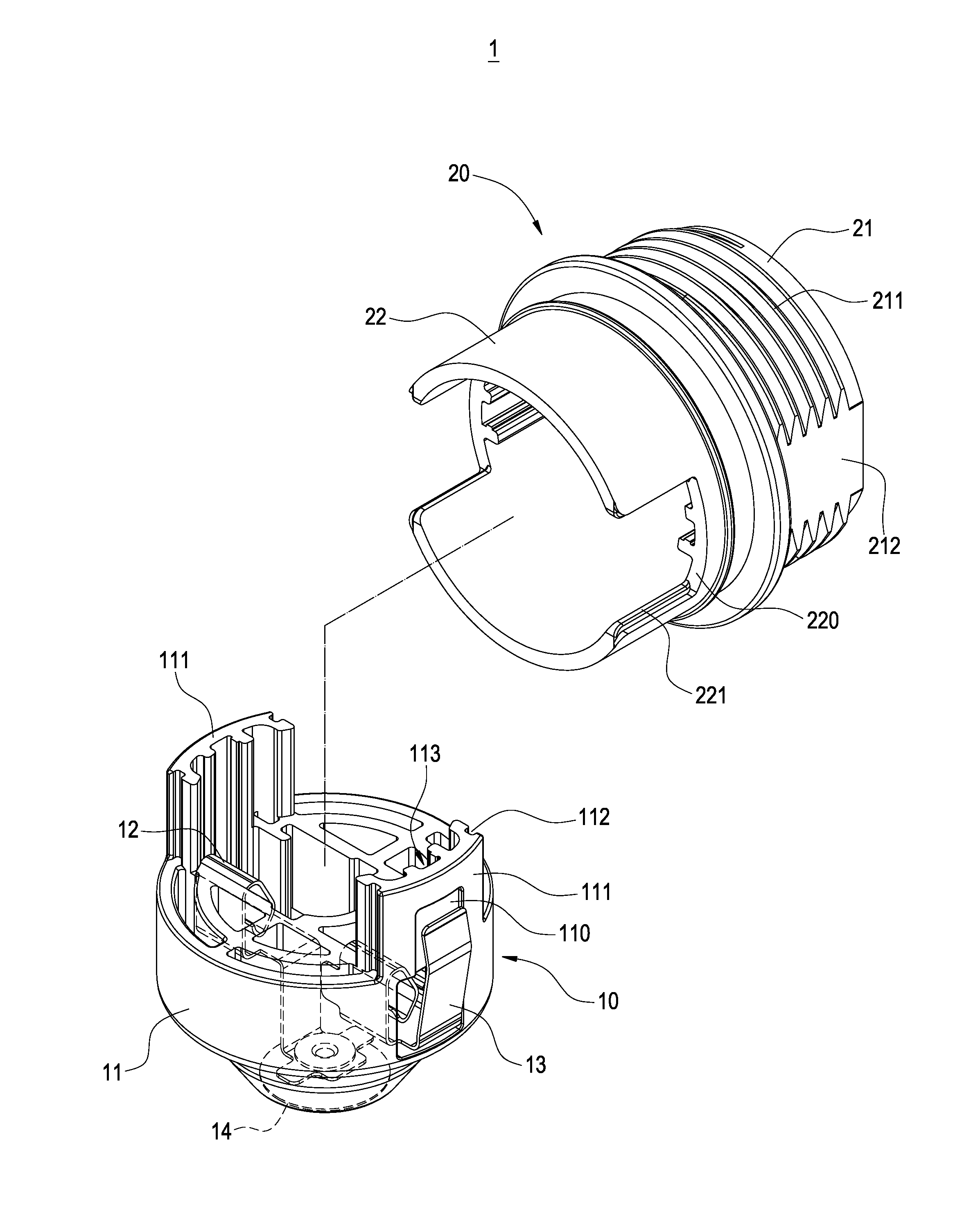
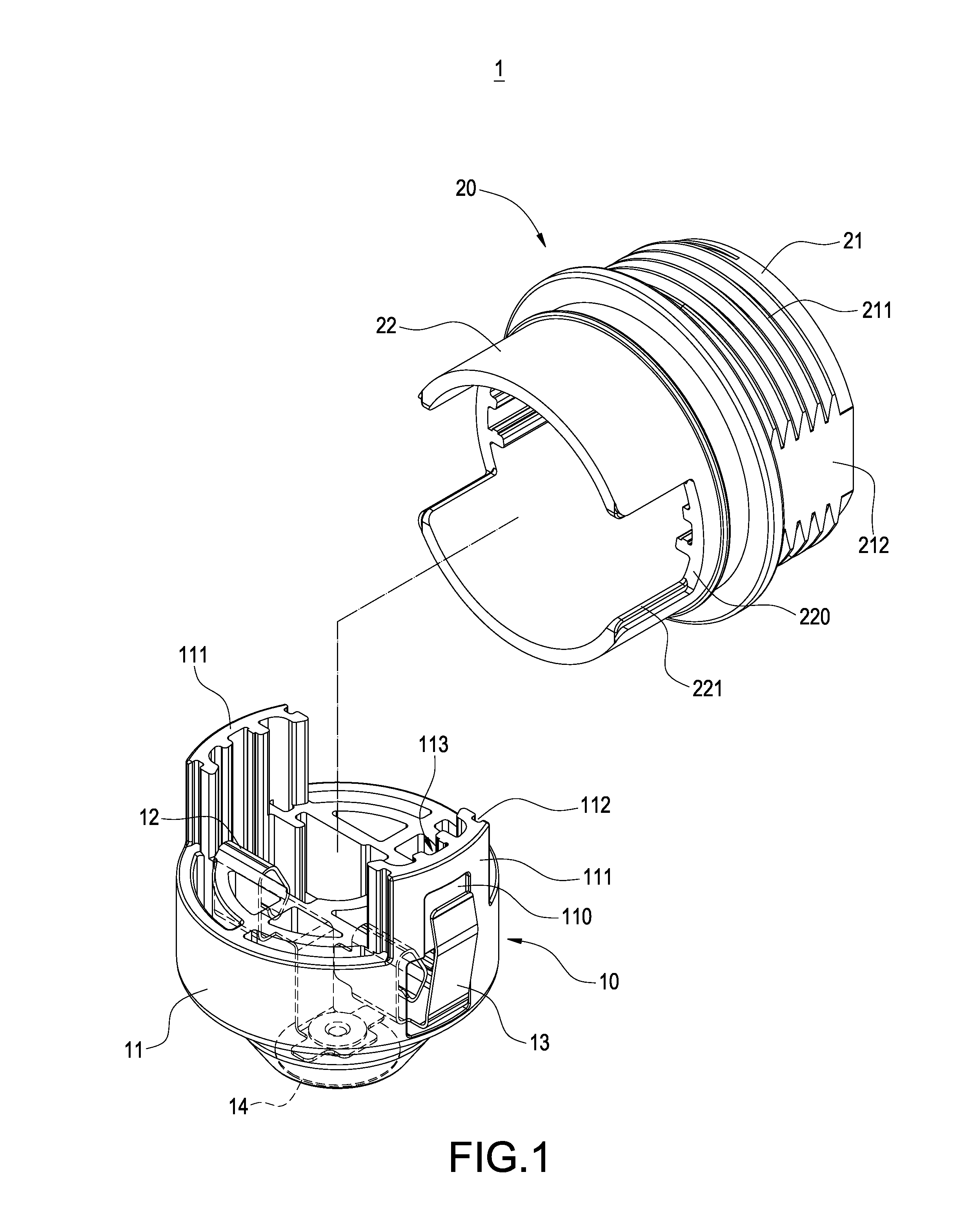
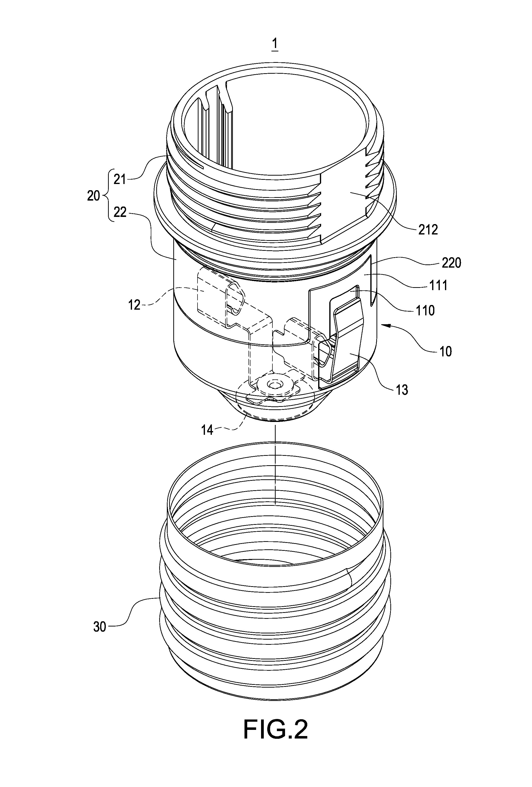
[0021]Please refer to FIG. 1, it depicts a perspective explosion schematic view of a lamp head assembly with positioning structures of the present invention. The lamp head assembly 1 includes a conducting head 10 and a supporting barrel 20. The supporting barrel 20 is inserted on the conducting head 10 and aligned each other. Thus the supporting barrel 20 corresponding to the conducting head 10 will not loosen in the horizontal direction. The detail structures will be described later.

[0022]The conducting head 10 includes an insulating seat 11, a first conducting plate 12, a conduction piece 14 and a second conducting pla...


PUM


Abstract

The present invention provides a lamp head assembly with positioning structures for combining with a lamp base. The lamp head assembly includes a conducting head and a supporting barrel. The conducting head has an insulating seat, a first conducting plate and a second conducting plate and a conduction piece. The conduction piece is electrically connected with the first conducting plate. A portion of the second conducting plate is protruded out of the insulating seat, and an end of the insulating seat is formed with a inserting plate. The supporting barrel includes a supporting section connected and an assembling section; wherein, the supporting barrel is assembled on the conducting head through a positioning of the inserting plate and the slot.

Description

BACKGROUND OF THE INVENTION[0001]1. Field of the Invention[0002]The present invention generally relates to a lamp head assembly and, in particular to a lamp head assembly used in an LED bulb.[0003]2. Description of Related Art[0004]Because LEDs have characteristics of quick response, small size and low pollution etc., LEDs are gradually replaced incandescent lamps for saving energy and protecting environment.[0005]Commercially available LED bulb has a lamp base and a lamp head connecting with the lamp base. There is an LED assembly disposed in the lamp base, and a conducting threaded section and an electrically bump are provided on the lamp head. Moreover, two wires are accommodated in the lamp base. An end of one wire is soldered on the circuit board, and the other end is soldered on a conducting threaded section. Besides, an end of the other wire is soldered on the circuit board and the other end is soldered on the electrically bump for configuring as a circuit loop.[0006]However,...

Claims


Application Information

Patent Timeline
Patent Type & Authority Patents(United States)
IPC IPC(8): H01R33/00H01R33/22H01R33/02H01R13/66F21V15/00B60Q3/04H01R33/08F21K99/00H01R33/09F21V23/02F21Y101/02
CPCF21K9/1355H01R33/09H01R33/22F21V23/02F21Y2101/02F21K9/23F21Y2115/10
Inventor YANG, CHIH-HUANSUNDO, ALAN MICHAEL JAMISOLAMIN
Owner AMPHENOL LTW TECH
Why Eureka
Try Eureka