System and method for reducing modal coupling of combustion dynamics

a technology of combustion dynamics and modal coupling, which is applied in the direction of combustion types, machines/engines, lighting and heating apparatus, etc., can solve the problems of increasing the production of carbon monoxide and unburned hydrocarbons, accelerating the wear of the fuel nozzle in a relatively short amount of time, and the chemical reaction rate of the combustion gas, etc., to achieve different combustion instability frequencies, reduce coherence, and reduce the effect of coheren

Active Publication Date: 2015-10-06
GENERAL ELECTRIC CO
View PDF8 Cites 13 Cited by
  • Summary
  • Abstract
  • Description
  • Claims
  • Application Information

AI Technical Summary

Benefits of technology

[0009]One embodiment of the present invention is a system for reducing coherence and, therefore, modal coupling of combustion dynamics that includes first and second combustors arranged about an axis, where each combustor includes a fuel nozzle and a combustion chamber downstream from the fuel nozzle. Each fuel nozzle includes an axially extending center body, a shroud that circumferentially surrounds at least a portion of the axially extending center body, a plurality of vanes that extend radially between the center body and the shroud. The vanes define a first fuel port at a first axial distance from the combustion chamber and have a leading edge at a second axial distance from the combustion chamber. Differences in the first axial distance and / or the second axial distance in the first combustor and the second combustor produce a combustion instability frequency in the first combustor that is different from the combustion instability frequency in the second combustor.
[0010]In some aspects, the center body may define a fuel port located at a third axial distance from the combustion chamber. In this and other aspects, a plurality of tube bundles may circumferentially surround each fuel nozzle, each tube bundle comprising a plurality of tubes and each tube comprising a fuel injectors extending through teach tube at a fourth axial distance from the combustor. In these and yet other aspects, the axial cap length of the first combustor may be different from the axial cap length of the second combustor. According to the teachings herein, one or more of the first axial distance, the second axial distance, the third axial distance, the fourth axial distance, and the axial cap length may be different in a first combustor as compared with a second combustor to produce different combustion instability frequencies between the two combustors.
[0011]The present invention may also include a method for reducing coherence and, therefore, modal coupling of combustion dynamics in a combustion system comprising a plurality of combustors. The method comprises providing a first combustor having a first liner defining a first combustion chamber, a first cap assembly, and at least one fuel nozzle housed within the first cap assembly and comprising an axially extending center body, a shroud circumferentially surrounding at least a portion of the axially extending center body and a plurality of vanes extending radially between the center body and the shroud, each vane defining at least a first fuel port located at a first axial distance from the first combustion chamber and further comprising a leading edge located at a second axial distance from the first combustion chamber; providing a second combustor having a second liner defining a second combustion chamber, a second cap assembly, and at least one fuel nozzle housed within the second cap assembly and comprising an axially extending center body, a shroud circumferentially surrounding at least a portion of the axially extending center body and a plurality of vanes extending radially between the center body and the shroud, each vane defining at least a first fuel port located at a first axial distance from the second combustion chamber and further comprising a leading edge located at a second axial distance from the second combustion chamber; wherein at least one of (i) the first axial distance in the first combustor is different from the first axial cap distance in the second combustor; and (ii) the second axial distance in the first combustor is different from the second axial distance in the second combustor.

Problems solved by technology

However, higher combustion gas temperatures may also promote flame holding conditions in which the combustion flame migrates toward the fuel being supplied by the fuel nozzles, possibly causing accelerated wear to the fuel nozzles in a relatively short amount of time.
Conversely, a lower combustion gas temperature associated with reduced fuel flow and / or part load operation (turndown) generally reduces the chemical reaction rates of the combustion gases, increasing the production of carbon monoxide and unburned hydrocarbons.
Although effective at enabling higher operating temperatures while protecting against flame holding and controlling undesirable emissions, at particular operating conditions, some combustors may produce combustion instabilities that result from an interaction or coupling of the combustion process or flame dynamics with one or more acoustic resonant frequencies of the combustor.
It has been observed that, in some instances, combustion dynamics may reduce the useful life of one or more combustor and / or downstream components.
For example, the combustion dynamics may produce pressure pulses inside the fuel nozzles and / or combustion chambers that may adversely affect the high cycle fatigue life of these components, the stability of the combustion flame, the design margins for flame holding, and / or undesirable emissions.
Alternately, or in addition, combustion dynamics at specific frequencies and with sufficient amplitudes, that are in-phase and coherent, may produce undesirable sympathetic vibrations in the turbine and / or other downstream components.
This selective frequency shifting reduces the ability of the combustor system tone to cause a vibratory response in downstream components and also encourages destructive interference from combustor-to-combustor, reducing the amplitudes of combustion dynamics.

Method used


Image

  • System and method for reducing modal coupling of combustion dynamics
  • System and method for reducing modal coupling of combustion dynamics
  • System and method for reducing modal coupling of combustion dynamics

Examples


first embodiment

[0046]The combustion dynamics associated with multiple combustors 14 incorporated into the gas turbine 10 may either constructively or destructively interfere with one another to increase or decrease, respectively, the amplitude and / or coherence of the combustion dynamics associated with the gas turbine 10. In particular embodiments, the combustion dynamics associated with one or more combustors 14 may be adjusted and / or tuned to affect the interaction with the combustion dynamics of another combustor 14 and, thus, the combustion dynamics associated with the gas turbine 10. For example, FIG. 7 illustrates a system for reducing coherence and, therefore, modal coupling of combustion dynamics according to the present invention.

[0047]In the particular embodiment shown in FIG. 7, multiple combustors 14 (having fuel nozzles 34, as shown in FIGS. 3 and 6) have been arranged about an axis 78. The axis 78 may coincide, for example, with the rotor 18 in the gas turbine 10 that connects the co...

second embodiment

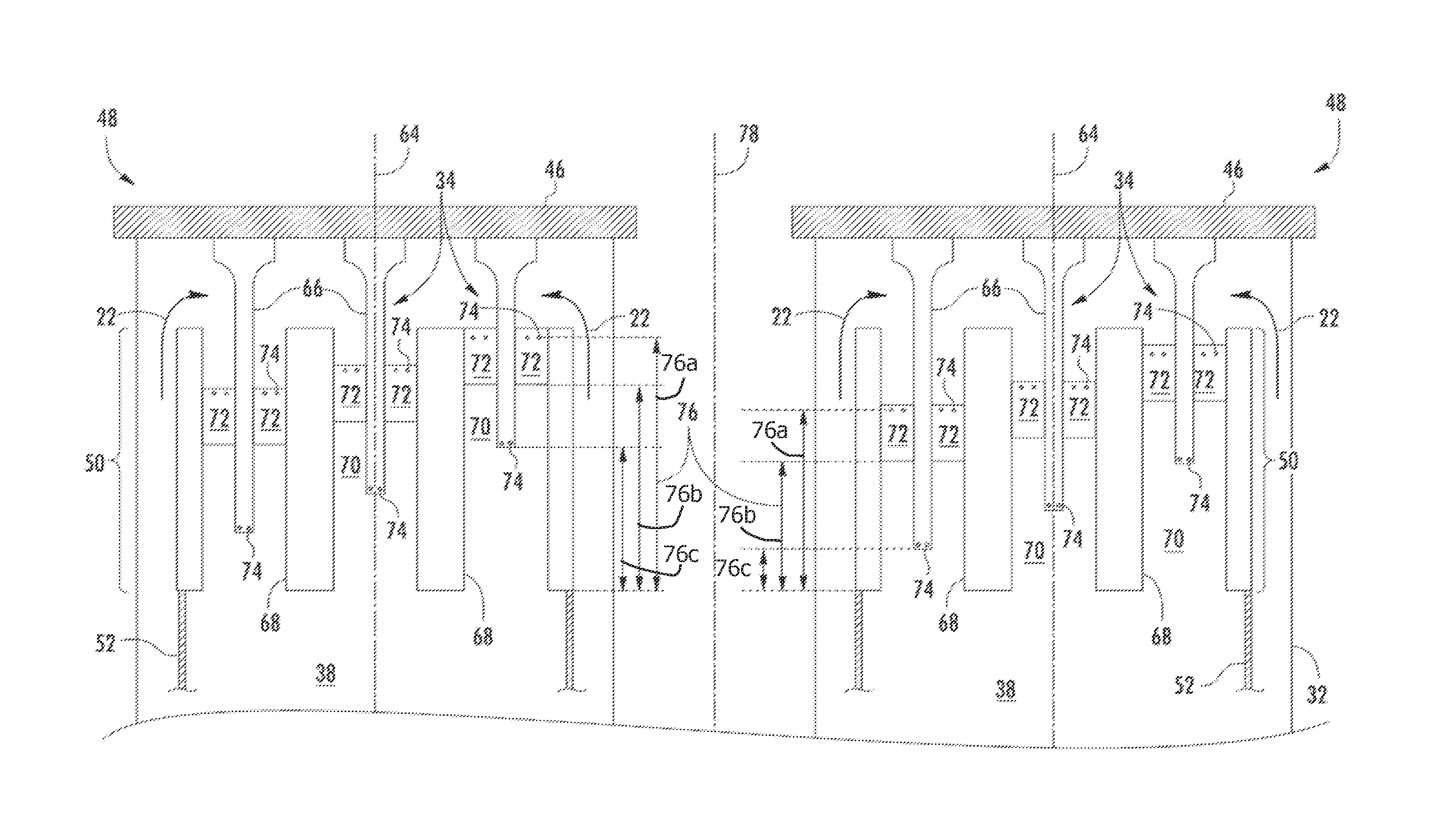
[0052]FIG. 8 provides a system for reducing combustion dynamics according to the present invention. As shown in FIG. 8, each combustor 14 again includes multiple fuel nozzles 34 with the combustion chamber 38 downstream from the fuel nozzles 34 as previously described. In addition, the axial positions of the fuel ports 74 and / or the vanes 72 may be the same or different in each combustor 14.

[0053]In the specific embodiment shown in FIG. 8, for example, the axial distances 76a, 76c between the fuel ports 74 and the combustion chamber 38 and the axial distances 76b between the vanes 72 and the combustion chamber 38 are different within the same combustor 14, but the axial positions of the fuel ports 74 and the vanes 72 relative to the end cover 46 are repeated in both of the combustors 14. It is contemplated that such a configuration may be applied to all of the combustors 14 in an array of combustors of the gas turbine, or may be applied to some sub-set of “n” combustors 14 in the ar...

third embodiment

[0064]The combustion dynamics associated with multiple combustors 14 incorporated into the gas turbine 10 may either constructively or destructively interfere with one another to increase or decrease, respectively, the amplitude, coherence, and / or modal coupling of the combustion dynamics associated with the gas turbine 10. For example, FIG. 10 provides a system for reducing modal coupling of the combustion dynamics according to the present invention. In the particular embodiment shown in FIG. 10, multiple combustors 14 (as shown in FIGS. 5 and 9) have been arranged about an axis 100. The axis 100 may coincide, for example, with the rotor 18 in the gas turbine 10 that connects the compressor section 12 to the turbine section 16, although the present invention is not limited to the particular orientation of the axis 100 or the particular arrangement of the combustors 14 about the axis 100.

[0065]As shown in FIG. 10, each combustor 14 includes multiple tubes 36 arranged in pie-shaped t...


PUM


Abstract

A system and method for reducing combustion dynamics includes first and second combustors, and each combustor includes a fuel nozzle and a combustion chamber downstream from the fuel nozzle. Each fuel nozzle includes an axially extending center body, a shroud that circumferentially surrounds at least a portion of the axially extending center body, a plurality of vanes that extend radially between the center body and the shroud, a first fuel port through at least one of the plurality of vanes at a first axial distance from the combustion chamber, the plurality of vanes being located at a second axial distance from the combustion chamber. A second fuel port is provided through the center body at a third axial distance from the combustion chamber. The system further includes structure for producing a combustion instability frequency in the first combustor that is different from the combustion instability frequency in the second combustor.

Description

CROSS-REFERENCE TO RELATED APPLICATIONS[0001]The present application is a continuation-in-part application of (GE-241695-1) U.S. patent application Ser. No. 14 / 048,252, filed Oct. 8, 2013, which is a continuation application of U.S. patent application Ser. No. 13 / 590,302 and U.S. patent application Ser. No. 13 / 590,309, both of which were filed on Aug. 21, 2012, the disclosures of which are hereby incorporated by reference herein in their entirety.TECHNICAL FIELD[0002]The present invention generally involves a system and method for reducing modal coupling of combustion dynamics. In particular embodiments, the invention may be incorporated into a gas turbine or other turbo-machine.BACKGROUND[0003]Combustors are commonly used in industrial and commercial operations to ignite fuel to produce combustion gases having a high temperature and pressure. For example, gas turbines and other turbo-machines typically include one or more combustors to generate power or thrust. A typical gas turbin...

Claims


Application Information

Patent Timeline
Patent Type & Authority Patents(United States)
IPC IPC(8): F23R3/20F02C7/22F23D14/02F02C7/24F23R3/46F23R3/28
CPCF23R3/20F02C7/22F02C7/24F23D14/02F23R3/286F23R3/46F23R2900/00014
Inventor CROTHERS, SARAH LORIKRAEMER, GILBERT OTTO
Owner GENERAL ELECTRIC CO
Why Eureka
Try Eureka