
Short coherence interferometry for measuring distances

a technology of coherence and distance measurement, applied in the field of short coherence interferometry, can solve the problems of reduced sensitivity, increased measurement depth, and large cost of required structure, and achieve the effect of effective noise suppression and high yield of irradiated

Inactive Publication Date: 2015-10-13
CARL ZEISS MEDITEC AG
View PDF37 Cites 0 Cited by
  • Summary
  • Abstract
  • Description
  • Claims
  • Application Information

AI Technical Summary

Benefits of technology

[0016]The object of the invention is therefore to create a short-coherence interferometer arrangement or a short-coherence interferometry method which is both insensitive to axial sample movements and allows a high yield of irradiated and reflected radiation for partly-absorbing or -reflecting objects and permits effective noise suppression.

Problems solved by technology

A disadvantage of SD-OCDR systems is the maximum measurement range size, which is limited by the spectrometer resolution, and the reduction in sensitivity which increases with the measurement depth.
The required structure is also much more expensive.

Method used


Image

  • Short coherence interferometry for measuring distances
  • Short coherence interferometry for measuring distances
  • Short coherence interferometry for measuring distances

Examples


Embodiment Construction

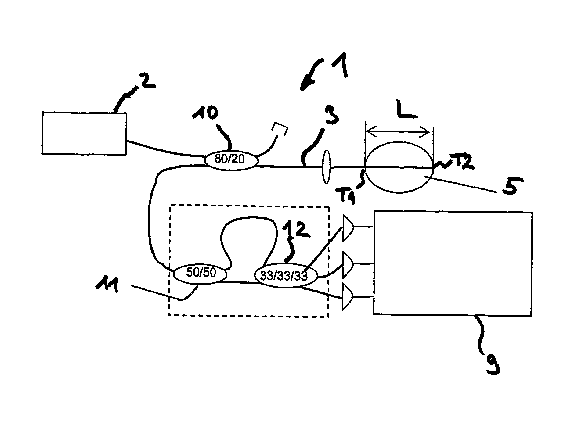
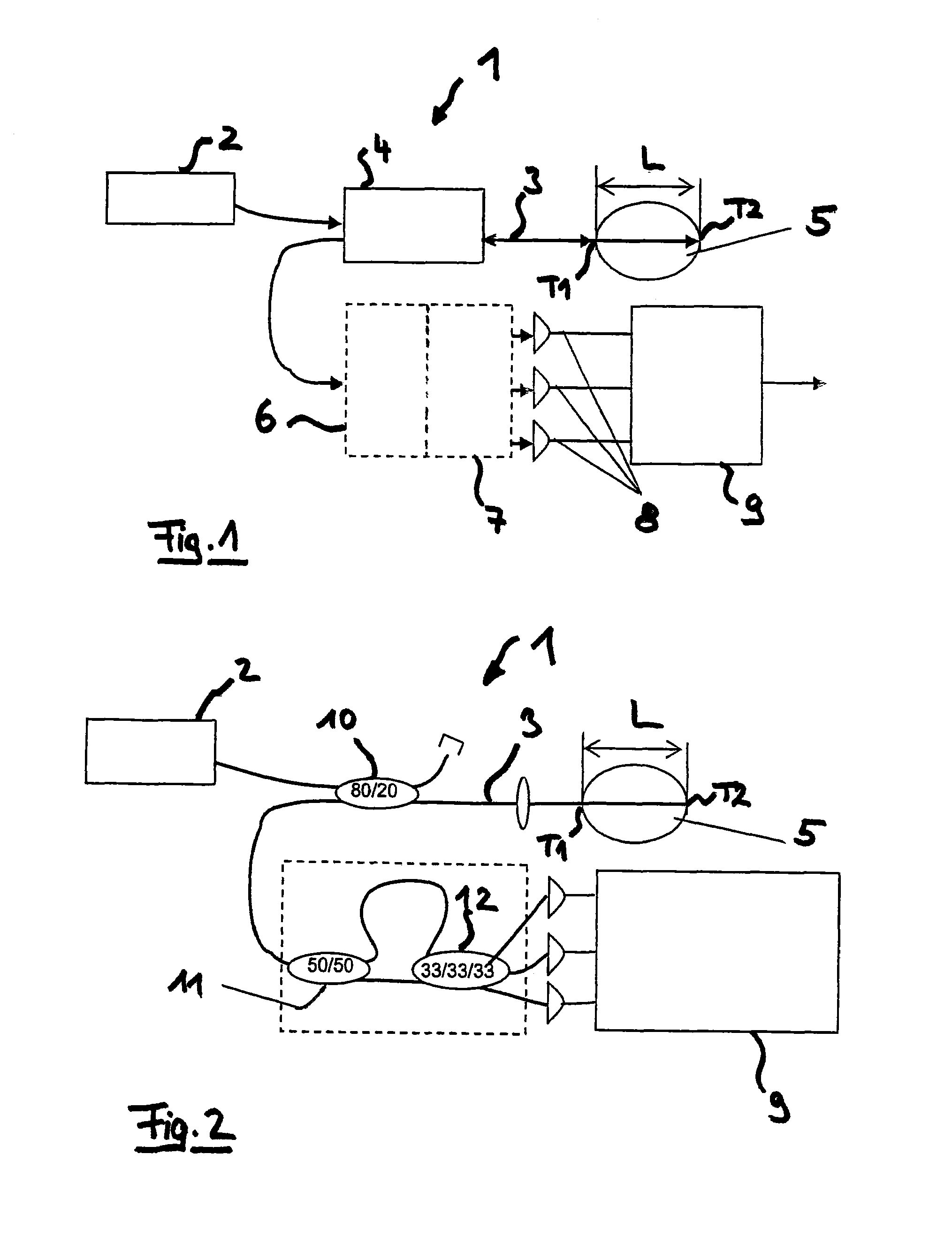
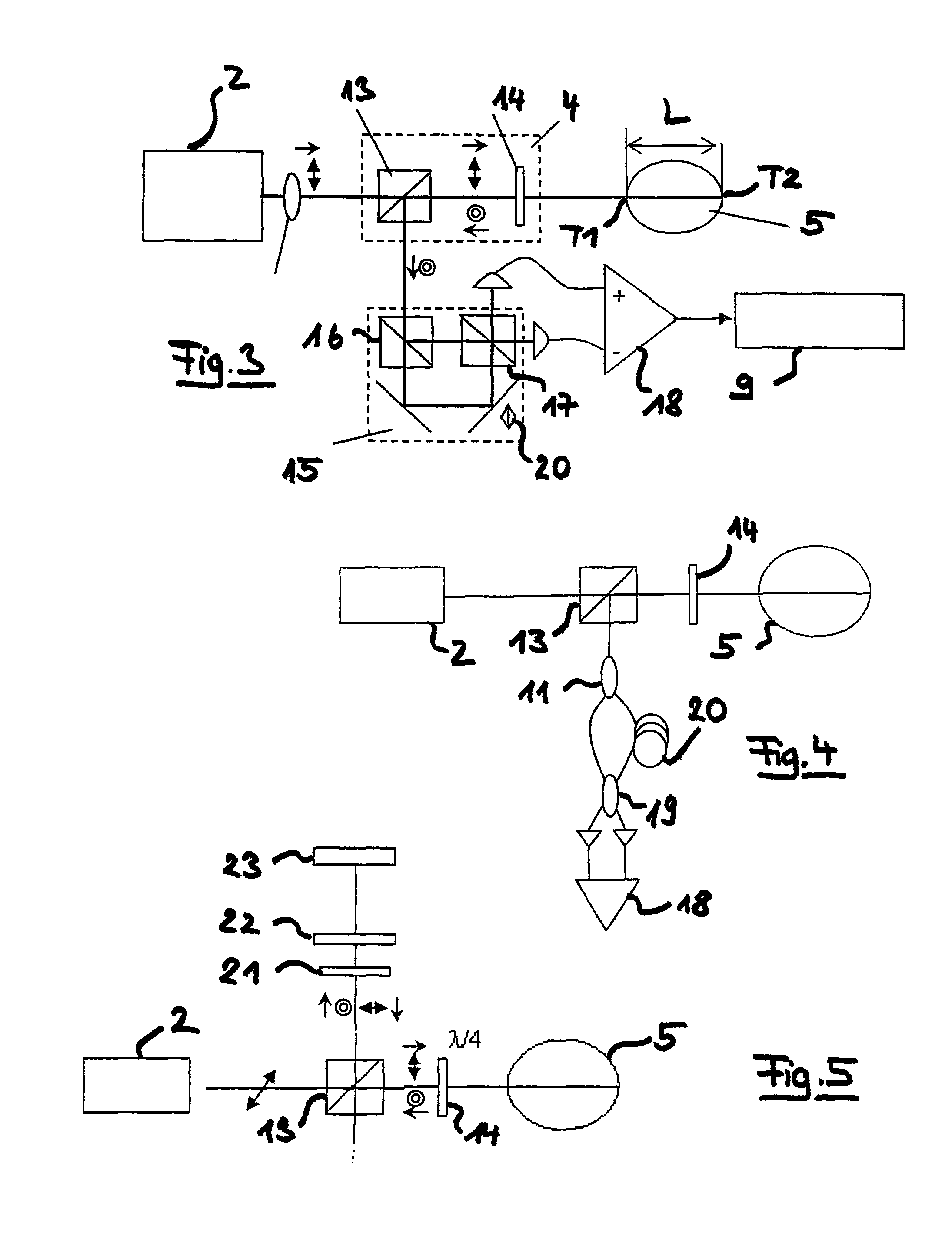
[0042]FIG. 1 shows schematically an interferometer apparatus 1 in the form of an eye-length measuring device, wherein this realization relates merely to an exemplary field of application of the interferometer apparatus 1, to which extent it is not be understood as limitative.

[0043]In apparatus 1, radiation of a radiation source 2 is conducted as measurement radiation 3 into a measurement beam path where it is directed onto the measurement object, here formed by an eye 5, i.e. the sample. The sample has axially spaced regions, here represented schematically as regions T1 and T2 of the eye 5, for example the front surface of the cornea, the rear surface of the cornea, the front surface of the lens, the rear surface of the lens or the fundus. Starting from the vertex of the front surface of the cornea as region T1 and the fundus as region T2, the axial distance between these regions gives the optical eye length L. The illumination of the areas T1 and T2 can also be influenced with sing...


PUM


Abstract

A short coherence interferometer for measuring several axially spaced-apart regions of a sample, especially of an eye, which has a measuring optical path, through which the measuring radiation falls on the sample, a tunable interferometer for the axial, relative retardation of parts of the radiation, wherein the axial relative retardation is assigned to the axial spacing of the regions and a detector for producing an interference signal from interfering measurement radiation, scattered or reflected back from the sample as sample radiation. The tunable interferometer divides the sample radiation into two parts, which are axially relatively retarded and superimposed so as to interfere. During the superimposition, the tunable interferometer forms individual radiations, which represent quadrature components of the sample radiation, and the detector detects the individual radiations.

Description

PRIORITY CLAIM[0001]The present application is a National Phase entry of PCT Application No. PCT / EP2009 / 004264, filed Jun. 12, 2009, which claims priority from German Application Number 102008029479.9, filed Jun. 20, 2008, the disclosures of which are hereby incorporated by reference herein in their entirety.FIELD OF THE INVENTION[0002]The invention relates to short-coherence interferometry methods for measuring several axially spaced regions of a sample, in particular an eye, wherein a measurement beam is directed onto the sample, beam parts are axially relatively delayed and an interference signal is generated from sample radiation formed by measurement radiation scattered or reflected back from the sample.[0003]The invention further relates to a short-coherence interferometer apparatus for measuring two axially spaced regions of a sample, in particular an eye, which has a measurement beam path through which measurement radiation falls onto the sample, a tuning interferometer devi...

Claims


Application Information

Patent Timeline
Patent Type & Authority Patents(United States)
IPC IPC(8): G01B9/02A61B3/10G01J5/60G01J3/45G01B11/02A61B3/15
CPCA61B3/1005A61B3/102G01B9/02079G01B9/02097G01B9/02091G01B2290/70A61B3/15
Inventor HACKER, MARTINEBERSBACH, RALFPABST, THOMAS
Owner CARL ZEISS MEDITEC AG
Learn More