Double inlet centrifugal blower with peripheral motor

a centrifugal blower and peripheral motor technology, applied in the field of centrifugal blowers, can solve the problems of reducing the overall cooling efficiency of the blower, unacceptable noise, and large power consumption, and achieve the effects of reducing manufacturing costs, reducing noise output, and significantly improving the operating efficiency of the double inlet centrifugal blower

Active Publication Date: 2015-10-13
LTI HLDG INC
View PDF25 Cites 14 Cited by
  • Summary
  • Abstract
  • Description
  • Claims
  • Application Information

AI Technical Summary

Benefits of technology

[0007]By means of the present invention, the operating efficiency of a double inlet centrifugal blower may be significantly enhanced while simultaneously reducing noise output. Moreover, the arrangement of the present invention reduces manufacturing costs, and simplifies assembly.

Problems solved by technology

Conventional systems, however, often employ fans and blowers that are not well matched to the system pressures, or do not move air efficiently within the space constraints, and therefore result in unacceptable noise and relatively large power consumption.
Neither conventional design is optimal, due to the motor occupying valuable aerodynamic space, which reduces the overall cooling efficiency of the blower, and creates unwanted noise.
The hub motor approach also requires a hollow shaft and resultant manufacturing complexities associated with routing stator wires through a mounting shaft.
Such struts, as described above, inhibit aerodynamic efficiency.

Method used


Image

  • Double inlet centrifugal blower with peripheral motor
  • Double inlet centrifugal blower with peripheral motor
  • Double inlet centrifugal blower with peripheral motor

Examples


Embodiment Construction

[0018]The objects and advantages enumerated above together with other objects, features, and advances represented by the present invention will now be presented in terms of detailed embodiments described with reference to the attached drawing figures which are representative of various possible configurations of the invention. Other embodiments and aspects of the invention are recognized as being within the grasp of those having ordinary skill in the art.

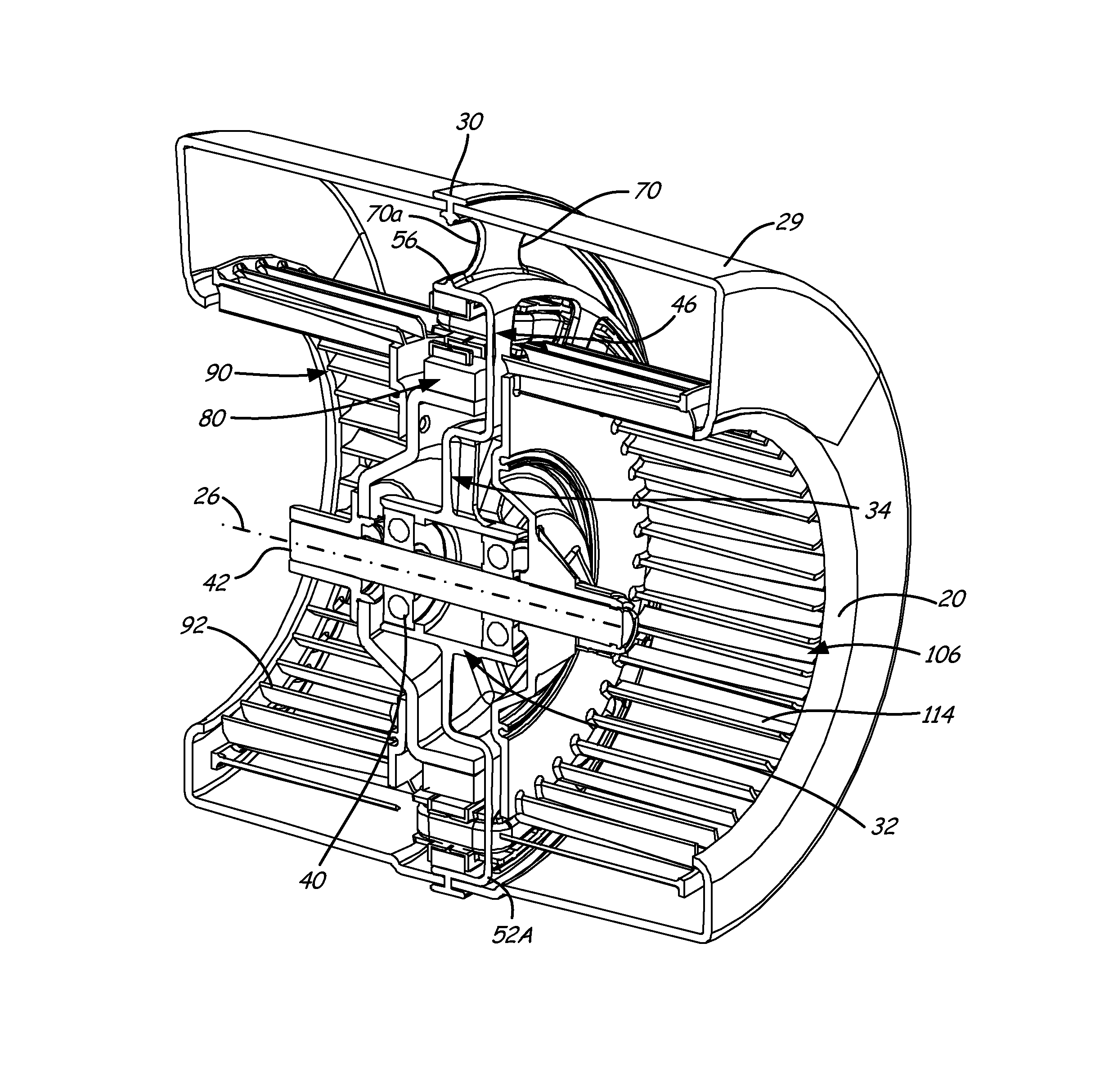
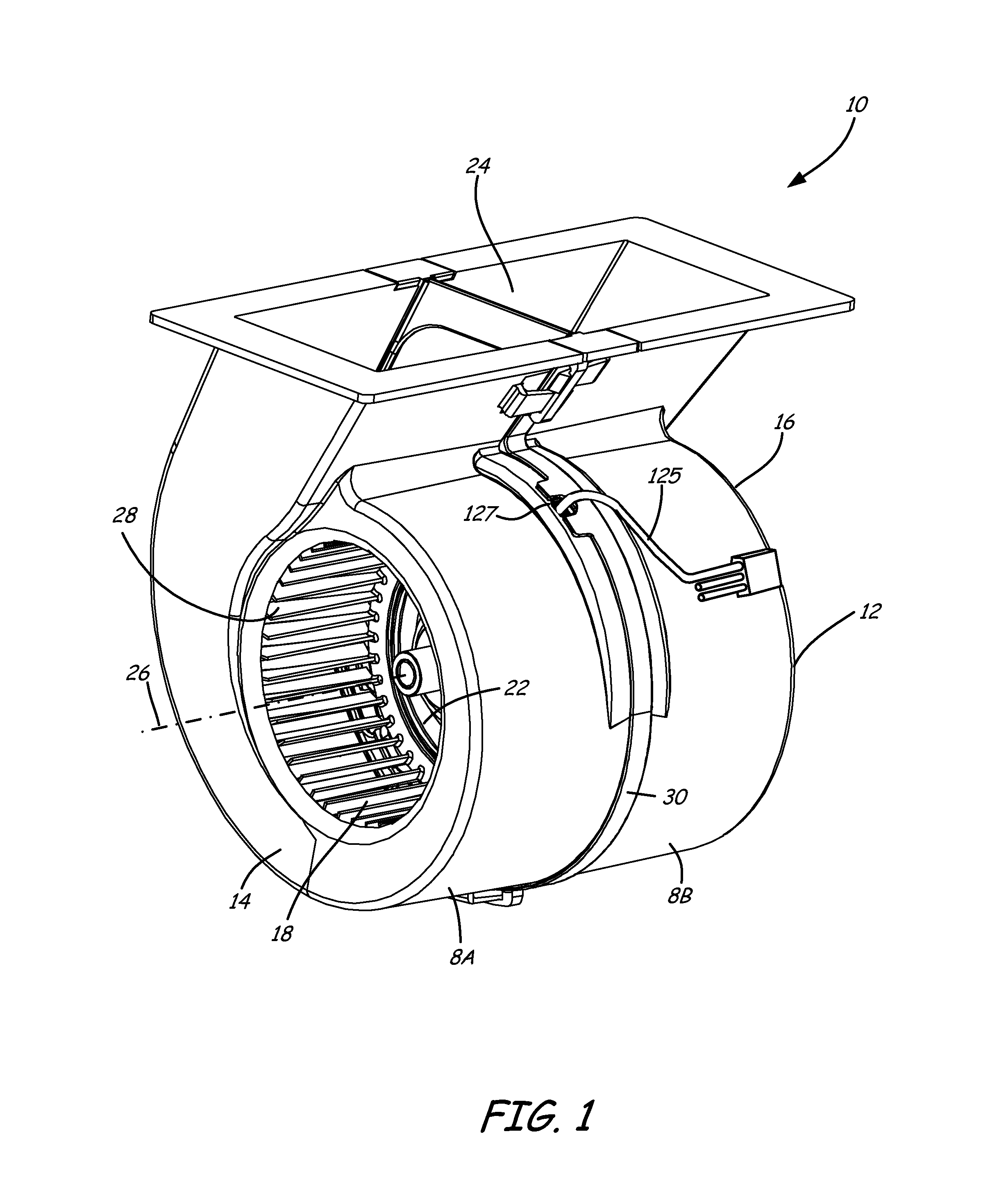
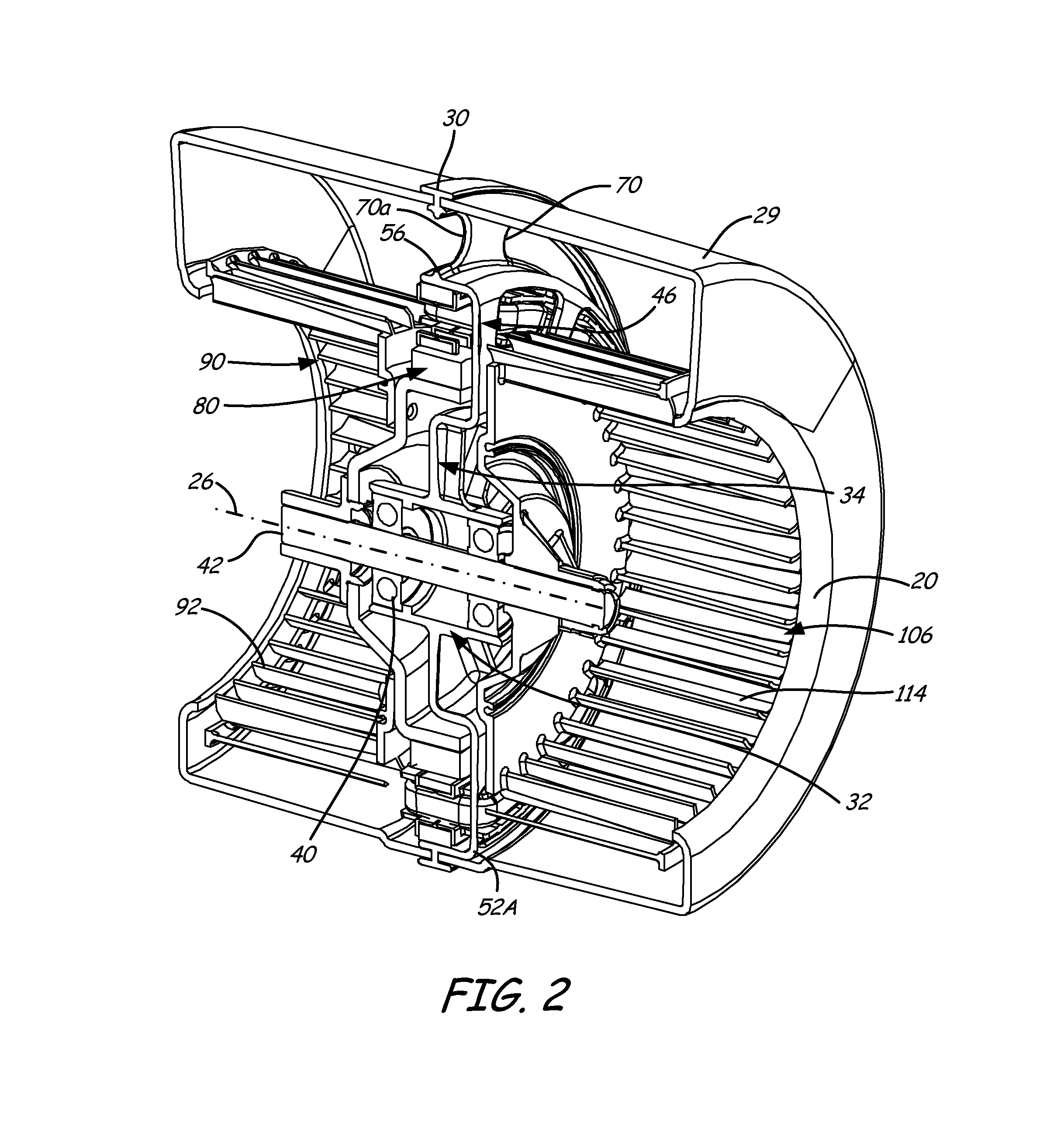
[0019]With reference now to the drawings, and first to FIG. 2, a centrifugal blower apparatus 10 includes a housing 12 having a first scroll-shaped side 14 with a first air inlet 18, and a second scroll-shaped side 16 with a second air inlet 20. First and second air inlets 18, 20 open to a blower chamber 22 that is in fluid communication with an air outlet 24 of housing 12. It is contemplated that housing 12 may be configured as needed, including in a generally conventional configuration employing an expanding scroll-shape in the ou...


PUM


Abstract

A centrifugal blower apparatus includes a scroll-shaped housing with first and second air inlets which open to a blower chamber that is in fluid communication with an air outlet. The blower includes a motor to drive an impeller, wherein the motor is secured to a frame that is coupled with the housing in a manner to substantially enhance aerodynamic performance of the blower.

Description

FIELD OF THE INVENTION[0001]The present invention relates to centrifugal blowers generally, and more particularly to a double inlet centrifugal blower with an integrated drive motor that minimizes interference with air flow dynamics through the blower to enhance efficiency and reduce acoustic level.BACKGROUND OF THE INVENTION[0002]Demands for electronic equipment to increasingly provide higher-performance operation in smaller packages are ever present. Typically, such electronic equipment requires compact and highly efficient cooling systems to provide cooling air to power supplies, microprocessors, and related electronics that reside in the equipment. A typical cooling system involves moving air across one or more operating electronic components, such as printed circuit boards. The flow path layout, type of air moving device, and how well it is integrated into the system are each key elements in achieving desired cooling performance in a small package size.[0003]Air movers of vario...

Claims


Application Information

Patent Timeline
Patent Type & Authority Patents(United States)
IPC IPC(8): F04D17/00F04D17/16F04D25/06
CPCF04D25/0606F04D17/162
Inventor DICKINSON, ROGERHOYT, ROBERT A.
Owner LTI HLDG INC
Why Eureka
Try Eureka