Injection nozzle with multi-piece tip portion

a technology of injection nozzle and tip portion, which is applied in the field of injection molding apparatus, can solve the problems of low thermal conductivity, material wear resistance in many cases, and other leakage paths can appear, so as to reduce leakage, improve heat profile, and reduce the wear of the tip

Active Publication Date: 2015-10-20
OTTO MANNER INNOVATIONS
View PDF15 Cites 0 Cited by
  • Summary
  • Abstract
  • Description
  • Claims
  • Application Information

AI Technical Summary

Benefits of technology

[0013]In another embodiment of the invention the nozzle tip is coated to increase the lifetime, especially the wear resistance, of the nozzle tip. In some embodiments the coating for the nozzle tip is selected for each application. The coatings are selected from one of these materials: TiN (titanium nitride), TiC (titanium carbide), Ti(C)N (titanium carbide-nitride), and TiAlN (titanium aluminum nitride). In other embodiments the coating is made with DLC (Diamond-like carbon).
[0017]In operation this hot runner nozzle assembly provides an improved heat profile, reduced wear of the tip, and reduced leakage at the tip area under a wider operating processing window.

Problems solved by technology

If they are made of highly conductive materials, these materials are in many cases not very wear resistant.
Many of the materials that can be used for the nozzle tips used in hot runner nozzles and that have good wear resistance have low thermal conductivity.
Other leakage paths can further appear between other cooperating surfaces of the nozzle tip and tip seal that have small gaps caused by manufacturing errors or thermal expansion.

Method used


Image

  • Injection nozzle with multi-piece tip portion
  • Injection nozzle with multi-piece tip portion
  • Injection nozzle with multi-piece tip portion

Examples


Embodiment Construction

[0029]In this specification and in the claims, the use of the article “a”, “an”, or “the” in reference to an item is not intended to exclude the possibility of including a plurality of the item in some embodiments. It will be apparent to one skilled in the art in at least some instances in this specification and the attached claims that it would be possible to include a plurality of the item in at least some embodiments.

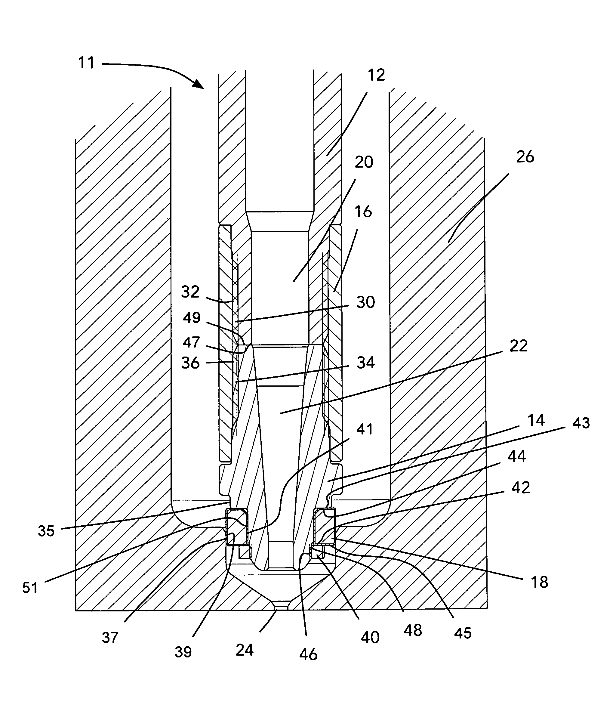
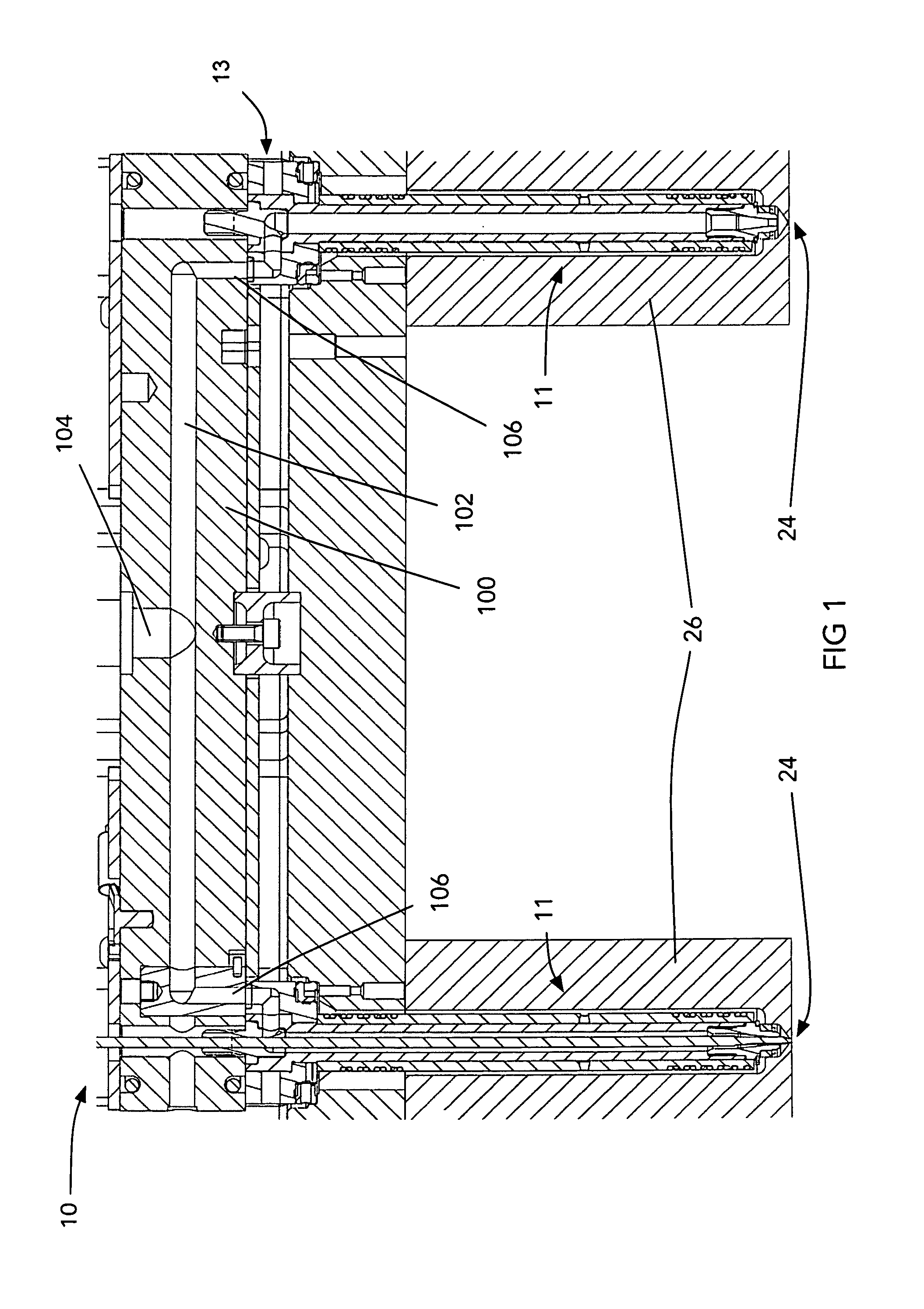
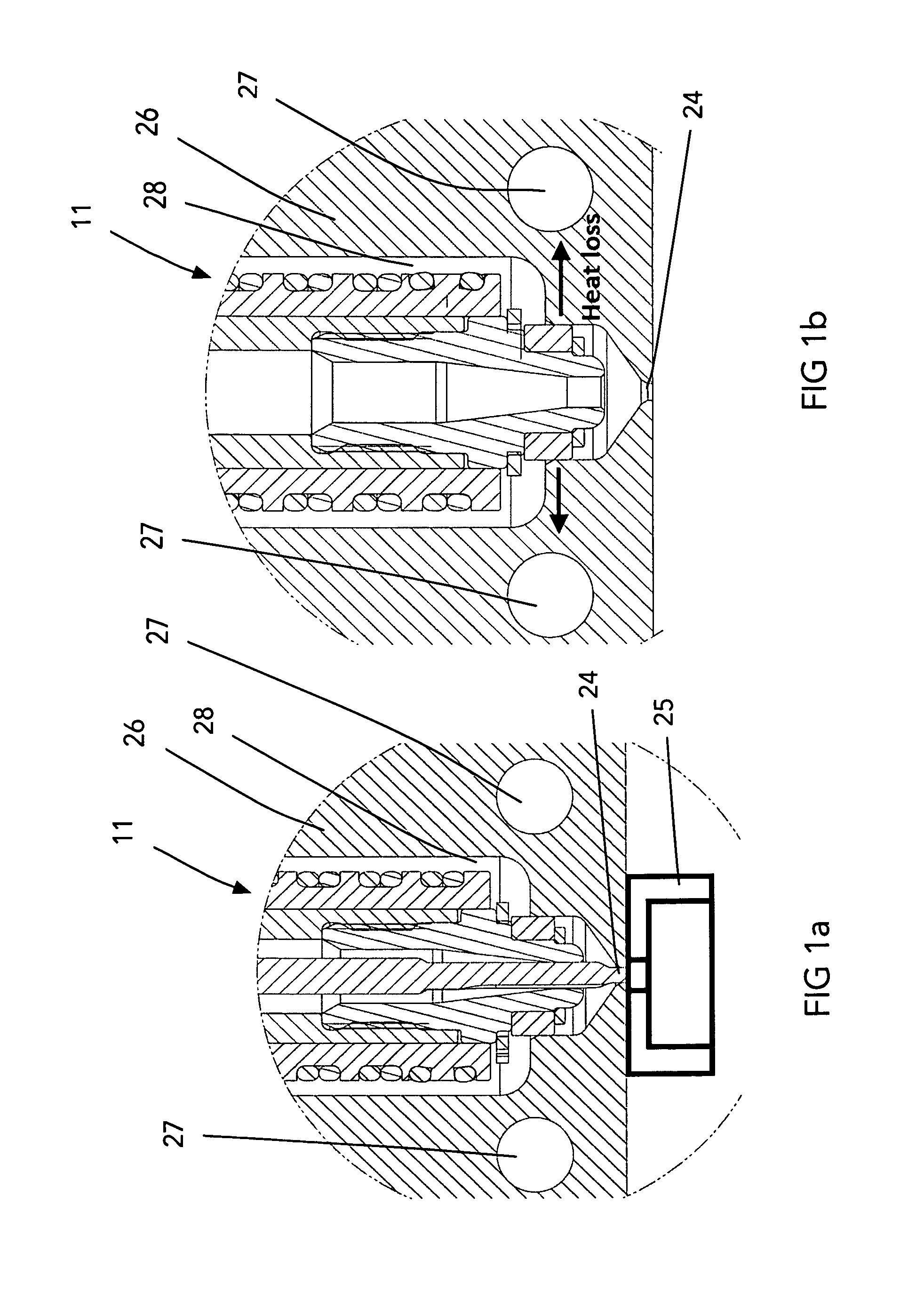
[0030]Reference is made to FIG. 1, which shows a portion of an injection molding machine 10. The injection molding machine 10 includes, among other things, a hot runner manifold 100 with a plurality of melt channel network 102 having an inlet 104 and a plurality of outlets 106. The machine 10 further including a plurality of injection nozzles 11 each of which receive melt from one of the outlets 106 and transport the melt to a gate 24 of a mold cavity 25 (see FIG. 1a) of a mold component 26. Only a portion of the mold component 26 is shown, however it will be underst...


PUM

PropertyMeasurementUnit
coefficient of thermal conductivityaaaaaaaaaa

Abstract

A hot runner nozzle assembly includes a nozzle heater, a hot runner nozzle, a nozzle tip, a nozzle tip seal surrounding the nozzle tip and a connecting element positioned to removably couple the tip seal to the nozzle tip and to create a first contact seal between the nozzle tip and the tip seal and a second annular contact seal between the tip seal and a mold component. The nozzle tip is made or shaped via a sintering process from a metal matrix composite (MMC) material having a first coefficient of thermal expansion. The tip seal is made or shaped from a ceramic based powder material, having a second coefficient of thermal expansion that is different from the first coefficient of thermal expansion. In operation this hot runner nozzle assembly provides an improved heat profile and a reduced leakage at the tip area under a wider operating processing window.

Description

CROSS-REFERENCE TO RELATED APPLICATIONS[0001]This application claims the benefit of U.S. Patent Application No. 61 / 804,602, filed Mar. 22, 2013, the contents of which are incorporated herein by reference in their entiretyFIELD OF THE INVENTION[0002]The present disclosure relates to an injection molding apparatus and more particularly to hot runner injection nozzles made of several cooperating parts.BACKGROUND OF THE INVENTION[0003]Hot runner injection nozzles are known. These nozzles are made of several parts designed to meet injection molding operating conditions for various materials and for various applications. These parts are made of various materials that need to be manufactured with high accuracy, low tolerances and also configured to be machine-able with available manufacturing equipment. These hot runner nozzles and the associated parts need to be designed and made to be easy to assemble and service in the field.[0004]An area at the end of the nozzle is the nozzle tip area,...

Claims


Application Information

Patent Timeline
Patent Type & Authority Patents(United States)
IPC IPC(8): B29C45/20B29C45/27B29C45/17
CPCB29C45/278B29C45/1734B29C45/1735B29C2045/2787B29K2995/0012B29K2995/0013B29C45/20
Inventor SPULLER, SWENOLARU, GHEORGHE GEORGE
Owner OTTO MANNER INNOVATIONS
Why Eureka
Try Eureka