High brightness inorganic electroluminescence device driven by direct current

a direct current, inorganic el technology, applied in the direction of discharge tube luminescnet screen, discharge tube/lamp details, luminescent compositions, etc., can solve the problems of fluorescent organic solid, weak element, and the characteristics of the electrode provided on the light emitting layer directly, or through hole injection layer or electron injection layer, etc., to prevent short circuit between the electrodes, reduce the effect of oxidation and oxidation

Inactive Publication Date: 2012-09-04
KURARAY CO LTD
View PDF36 Cites 0 Cited by
  • Summary
  • Abstract
  • Description
  • Claims
  • Application Information

AI Technical Summary

Benefits of technology

[0015]Further, the inorganic EL element of the present invention is characterized in that the thickness of the EL light emitter layer is 0.05 μm or more and 100 μm or less. Optimizing the thickness of the light emitter layer enables low voltage drive and prevention of short circuit between the electrodes.
[0016]Further, the inorganic EL element of the present invention is characterized in that the surfaces between the above described two electrode layers are both made of different compositions. Changing and optimizing the compositions of the surfaces between the electrodes allows to increase the performances, such as to increase the emission efficiency and the lifetime due to the improvement of the adhesion strength with the electrodes.
[0017]According to the present invention, there can be provided a DC driven inorganic EL emission element useful for mobile applications and other applications. In addition, a light source available for various applications can be provided by having high brightness.

Problems solved by technology

However, the above inorganic element requires to be applied with an alternative voltage of 100 V or more at a frequency in the range of several hundreds Hz to dozens KHz, being less and less used in mobile devices such as notebook computers and cellular phones that use batteries, due to the fact that the DC-AC conversion element is necessary and for other reasons.
However, a fluorescent organic solid which is a material of the light emitting layer of the organic EL element is weak against moisture, oxygen and other substances.
Also, the characteristics of the electrode provided on the light emitting layer directly, or through a hole injection layer or electron injection layer, are likely to deteriorate due to oxidation.
Thus, there is a problem that when the conventional organic EL element is driven in the atmosphere, the emission characteristic deteriorates rapidly.
Hei 11-329718), but the problem is not perfectly solved from the point of view of the lifetime.
However, in the case of the conventional direct current inorganic EL elements including those described in the above Patent Documents 3 and 4, mostly there is no description about the brightness, and the approach to realize high brightness has not been sufficiently carried out.

Method used


Image

  • High brightness inorganic electroluminescence device driven by direct current
  • High brightness inorganic electroluminescence device driven by direct current
  • High brightness inorganic electroluminescence device driven by direct current

Examples


example

[0029]The present invention will be described in grater detail with reference to the example and comparative example, but the present invention is not limited to these examples.

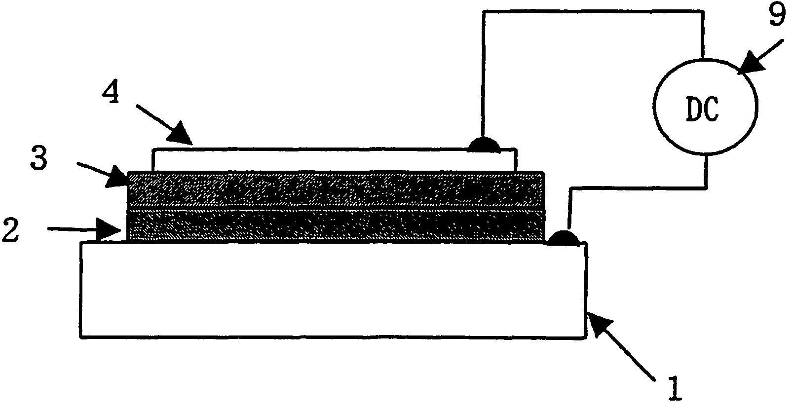
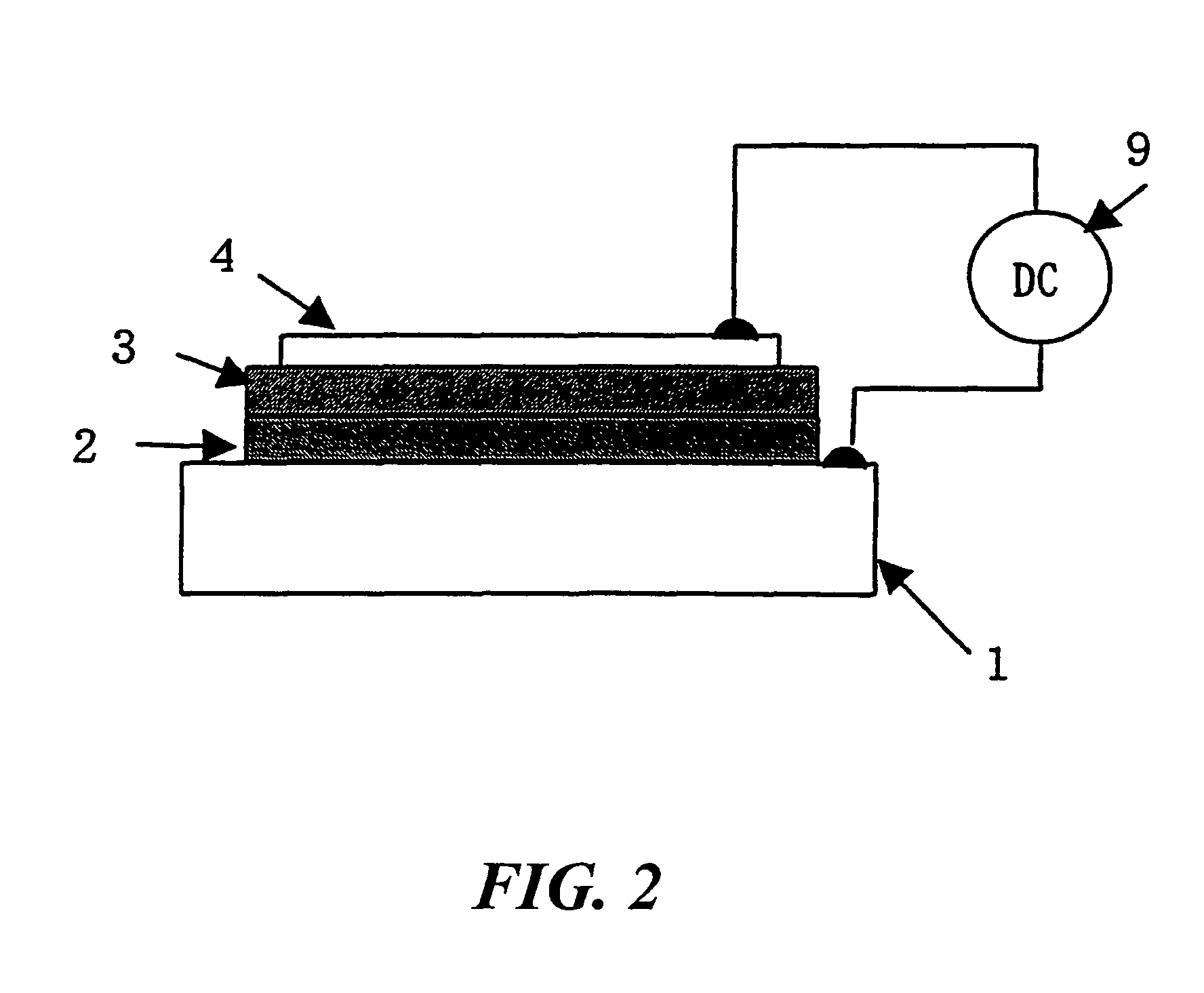
[0030]The EL element having the configuration shown in FIG. 2 has been produced.

(Production of Luminescent Material)

[0031]An amount of 100 g of zinc sulfide is blended with 0.27 g of manganese sulfide, 0.5 g of zinc oxide, 3 g of barium fluoride, 3 g of magnesium chloride, and 0.012 g of iridium chloride, and the blended materials are put in a reaction chamber of a high pressure-resistant container, followed by adding trinitrotoluene. The reaction container is sealed to reduce the pressure therein to 0.01 mmHg, and the reaction chamber is heated to about 450 degrees to induce an explosion. After confirmation that the explosion reaction has been generated within the container, the reaction chamber is cooled and the rough product is corrected. This is put into water and stirred, and then suspended solids are re...


PUM


Abstract

The present invention is characterized by a DC-driven inorganic EL element useful for mobile and other applications, the EL element including at least plural electrode layers, and a light emitter layer made of an inorganic composition, which is provided between the electrode layers, wherein the attainted brightness in the DC drive is 10000 cd / m2 or more.

Description

BACKGROUND OF THE INVENTION[0001]1. Field of the Invention[0002]The present invention relates to an inorganic EL element capable of emitting light with direct current.[0003]2. Description of the Related Art[0004]Electroluminescence (referred to as “EL” in the present invention) elements are roughly classified into inorganic EL elements and organic EL elements due to the difference of their light emitter materials. The inorganic EL element using an inorganic material for the light emitter has a characteristic that the emission lifetime is longer than that of the organic EL element using an organic material for the light emitter. Thereby the inorganic EL element has been put to practical use mainly for applications requiring high durability, such as cash register display units, in-vehicle monitors, and clock backlights.[0005]FIG. 1 is a perspective view showing a key portion of a representative configuration of a conventional inorganic EL element. An EL element 10 is a thin film EL el...

Claims


Application Information

Patent Timeline
Patent Type & Authority Patents(United States)
IPC IPC(8): H05B33/00H01L33/00
CPCC09K11/7428H05B33/145
Inventor UEDA, TADASHIYAMAUCHI, SEIKOHKANAMORI, JIROHAYASHI, YOSHISADA
Owner KURARAY CO LTD
Why Eureka
Try Eureka