Motor with air bearing structure

a technology of air bearings and motors, which is applied in the direction of shafts and bearings, dynamo-electric machines, supports/enclosements/casings, etc., can solve the problems of non-uniform air gap between the shaft and the rotor, non-uniform air gap can reduce the vibration of the shaft, and non-uniform air gap, so as to achieve more stabilization, less vibration, and increase the reliability of the motor

Inactive Publication Date: 2008-02-14
DELTA ELECTRONICS INC
View PDF2 Cites 0 Cited by
  • Summary
  • Abstract
  • Description
  • Claims
  • Application Information

AI Technical Summary

Benefits of technology

[0008]In view of the foregoing, the invention is to provide a motor with an air bearing structure. When rotating, the motor is more stabile and has less vibration since the distribution of partial magnetic filed is changed. Therefore, the reliability of the motor can be increased.
[0009]To achieve the above, the motor of the invention includes a shaft, a rotor, and a stator. The rotor is coupled to the shaft so that an air gap is formed therebetween to form the air bearing structure. The stator is coupled to the shaft and is located on a periphery of the rotor. The stator has a plurality of coils disposed therearound and has a magnetic body for changing a magnetic torque between the stator and the rotor. When the motor is operating, the rotor is forced by the magnetic torque and biased slightly toward the magnetic body so that the magnetic field distribution inside the motor can be changed. Therefore, the air gap between the shaft and the rotor at a place farther away the magnetic body is a little narrower than that near the magnetic body. That is, the air gap between the shaft and the rotor is non-uniform. Such a non-uniform air gap can reduce the vibration of the shaft when the rotor is rotating. Therefore, the conventional groove is not necessary in the motor of the invention.
[0010]As mentioned above, the non-uniform air gap can be performed by disposing a permanent magnet or a yoke close to the air bearing structure, changing the winding numbers of the coils of the stator, or decreasing the area of the iron ring of the stator so that the magnetic field can be changed. Thus, the air gap is non-uniform while the air bearing structure rotates so as to reduce the vibration of the shaft. Compared with the prior art, the invention utilizes the magnetic body to change the distribution of the magnetic field in the motor for stabilizing the shaft. In other words, it is unnecessary to process the shaft to form the conventional grooves. As a result, the air bearing structure of the invention can rotate stably so as to increase the reliability and lifetime of the motor.

Problems solved by technology

That is, the air gap between the shaft and the rotor is non-uniform.
Such a non-uniform air gap can reduce the vibration of the shaft when the rotor is rotating.
Thus, the air gap is non-uniform while the air bearing structure rotates so as to reduce the vibration of the shaft.

Method used


Image

  • Motor with air bearing structure
  • Motor with air bearing structure
  • Motor with air bearing structure

Examples


first embodiment

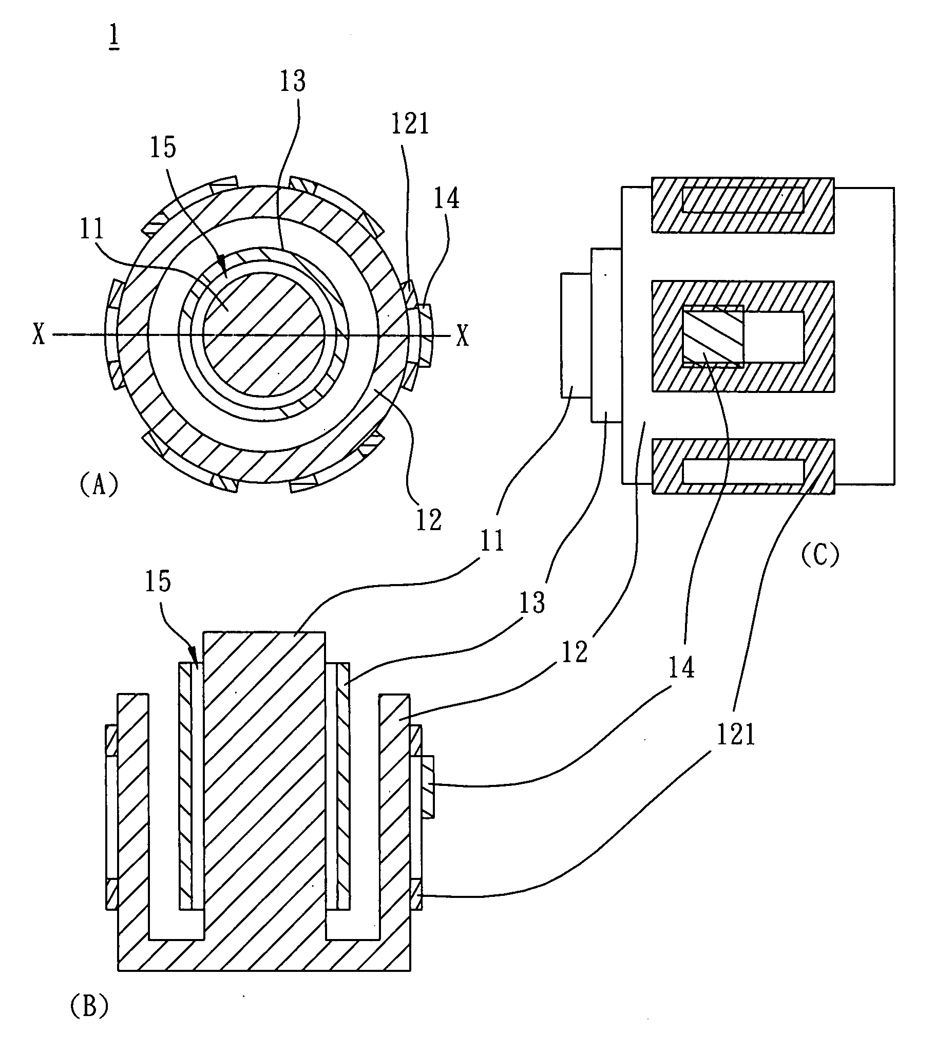
[0022]As shown in FIG. 1, a motor 1 according to the invention includes a shaft 11, a stator 12, a rotor 13 and a magnetic body 14. The stator 12 includes a plurality of coils 121. The rotor 13 is disposed between the shaft 11 and the stator 12, and an air gap 15 is formed between the rotor 13 and the shaft 11. The magnetic body 14 is disposed to any one of the coils 121. In the embodiment, the magnetic body 14 can be a permanent magnet, such as a magnet, a magnetite or a magnetic yoke. Alternatively, the magnetic body 14 can be a silicon steel sheet or a soft magnet made of iron, cobalt, nickel or alloys thereof. In more detail, the rotor 13, the shaft 11 and air gap 15 therebetween constitutes the air bearing structure. In the air bearing structure, the shaft 11 is an inner circular part, and the rotor 13 is an outer circular part.

[0023]In the embodiment, due to the magnetic torque caused by the magnetic body 14, the rotor 13 is biased toward the magnetic body 14 when the motor 1 ...

fourth embodiment

[0026]FIG. 4 shows a motor 2 according to the invention. The motor 2 includes a shaft 21, a stator 22 and a rotor 23. The stator 22 includes a plurality of coils 221. The rotor 23 is disposed between the shaft 21 and the stator 22 so as to form an air gap 25 between the shaft 21 and the rotor 23. The shaft 21, rotor 23 and air gap 25 constitute an air bearing structure, while the shaft 21 is an inner circular part of the air bearing structure and the rotor 23 is an outer circular part.

third embodiment

[0027]In this embodiment, the magnetic body as described in the first, second or third embodiment is unnecessary. Herein, any one of the coils 221 has a winding number different from others. This configuration can make the magnetic torque become non-uniform around the stator 22. As shown in FIG. 4, the winding number of a coil 24 is different from that of other coils 221. If the winding number of the coil 24 is greater than that of the other coils 221, the rotor 23 will be biased toward the winding 24 by the magnetic force of the coil 24. In this case, the air gap 25 is larger at a place near the winding 24. Alternatively, if the winding number of the winding 24 is less than that of other coils 221, the rotor 23 will be biased away from the winding 24 by the magnetic force of the winding 24. In this case, the air gap 25 is smaller at the place near the winding 24. Therefore, the winding 24 can cause the non-uniformity of the air gap 25 between the shaft 21 and the rotor 23, so that ...


PUM


Abstract

A motor with an air bearing structure includes a shaft, a rotor, a stator and a magnetic body. The rotor is coupled to the shaft and an air gap is formed therebetween, thereby forming the air bearing structure. The stator is coupled to the rotor and an air gap is formed therebetween. The magnetic body is disposed adjacent to the periphery of the stator.

Description

CROSS REFERENCE TO RELATED APPLICATIONS[0001]This Non-provisional application claims priority under 35 U.S.C. §119(a) on Patent Application No. 095129722 filed in Taiwan, Republic of China on Aug. 14, 2006, the entire contents of which are hereby incorporated by reference.BACKGROUND OF THE INVENTION[0002]1. Field of Invention[0003]The invention relates to a motor and in particular, to a motor with an air bearing structure.[0004]2. Related Art[0005]In present days, electronic products have been made smaller, and motors are more important than usual, especially the high speed motors. Accordingly, the relative techniques are developed rapidly. As the speed of the motor has been increased, the bearing and shaft must be manufactured with highly precise fitness, low friction coefficient, low vibration and longer product life. Air bearings can satisfy these requirements.[0006]To solve the problems of vibration and excess swing of the motor, the conventional air bearing is provided with gro...

Claims


Application Information

Patent Timeline
Patent Type & Authority Applications(United States)
IPC IPC(8): H02K7/08
CPCF16C33/107H02K7/09H02K7/086
Inventor CHANG, SEANCHANG, CHII-HOW
Owner DELTA ELECTRONICS INC
Why Eureka
Try Eureka