Supercharge Your Innovation With Domain-Expert AI Agents!

Pump/generator over-unity apparatus and method

a technology of pump and generator, applied in the direction of electric generator control, machines/engines, sustainable buildings, etc., can solve the problems of prior art not being available in the turbine art, technology providing the same or similar, heat loss, etc., to achieve low friction environment, maximize energy production, and minimal resistance and friction

Active Publication Date: 2015-10-20
BURNS III GORDON CHARLES +2
View PDF49 Cites 5 Cited by
  • Summary
  • Abstract
  • Description
  • Claims
  • Application Information

AI Technical Summary

Benefits of technology

The invention described in this patent text has several advantages. Firstly, it uses magnets instead of traditional bearings and other moving parts, which reduces friction and allows the device to operate with minimal resistance. Secondly, it has a helical propeller or impeller that maximizes energy produced in a pipeline without restricting the flowing matter. Lastly, it has no external motor to drive the impellers, making it more compact than other pumps. These technical effects make the invention more efficient, reliable, and compact.

Problems solved by technology

Friction creates heat and loss of potential energy as well as wear on parts.
Nor is there technology providing the same or similar results in the current industry, such as with wind farms, hydroelectric dams and solar power.
Therefore, the prior art would not be available in the turbine art, despite their use of impellers for generating electricity.
Schöb would not teach the use of generating coils on the outside of the cylinder as in the invention because such use would be non-enabling, interfering with its drive and bearing coils.

Method used


Image

  • Pump/generator over-unity apparatus and method
  • Pump/generator over-unity apparatus and method
  • Pump/generator over-unity apparatus and method

Examples


Embodiment Construction

[0047]The present invention will now be described more fully hereinafter with references to the accompanying drawings, in which the preferred embodiment of the invention is shown. This invention may, however, be embodied in different forms and should not be construed as limited to the embodiments set forth herein. Rather, the illustrative embodiments are provided so that this disclosure will be thorough and complete, and will fully convey the scope of the invention to those skilled in the art. It should be noted, and will be appreciated, that numerous variations may be made within the scope of this invention without departing from the principle of this invention and without sacrificing its chief advantages. Like numbers refer to like elements throughout.

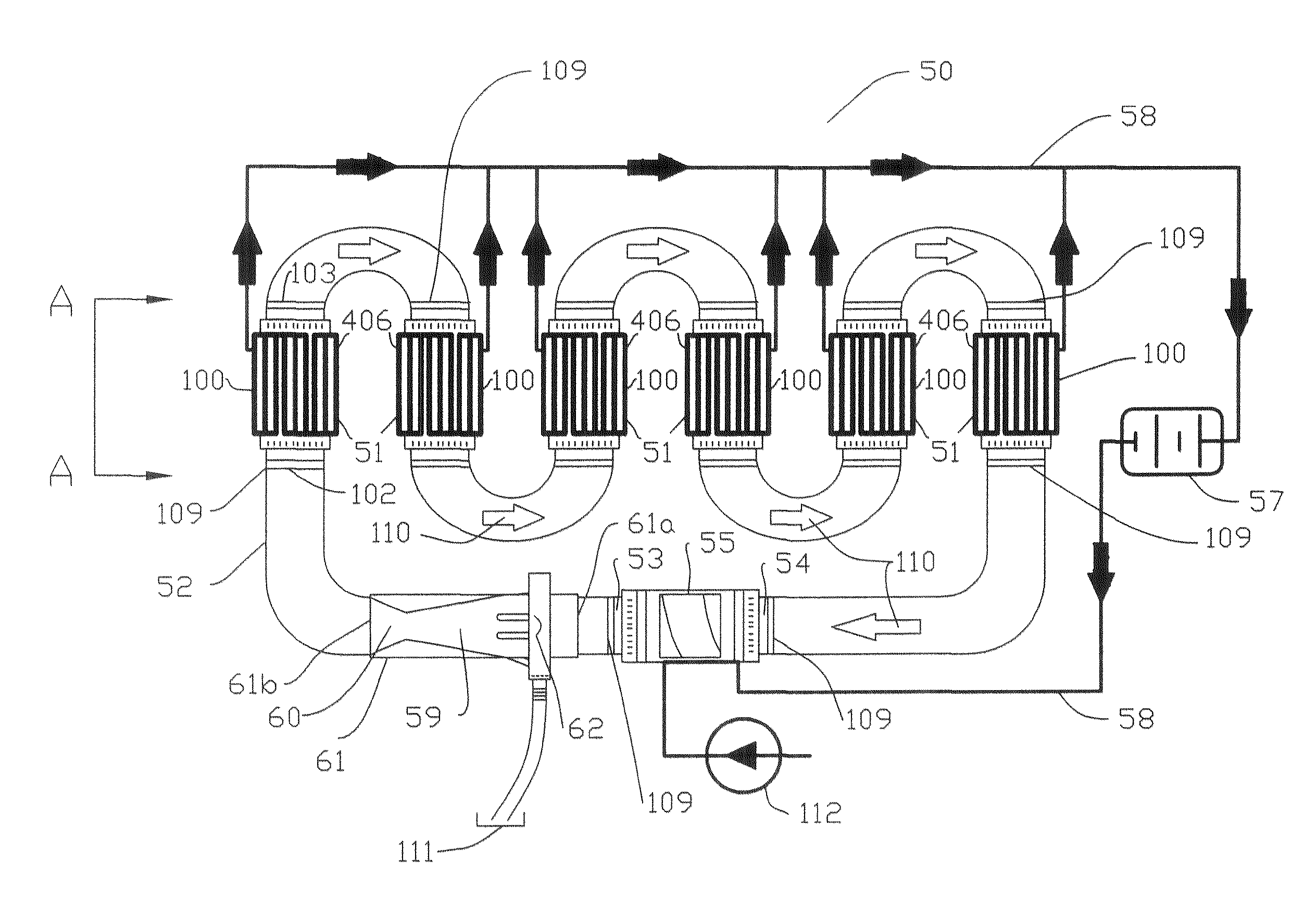
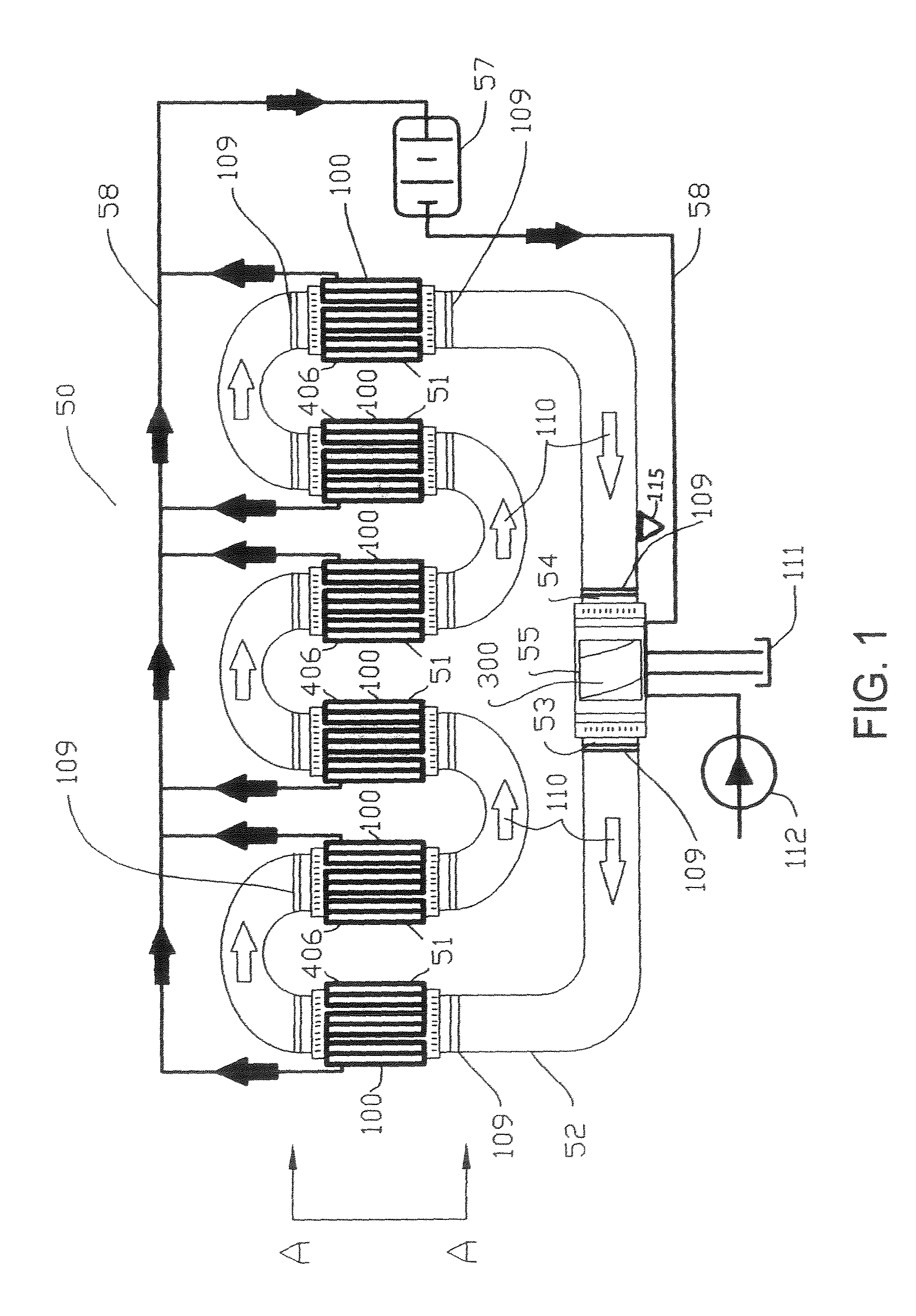
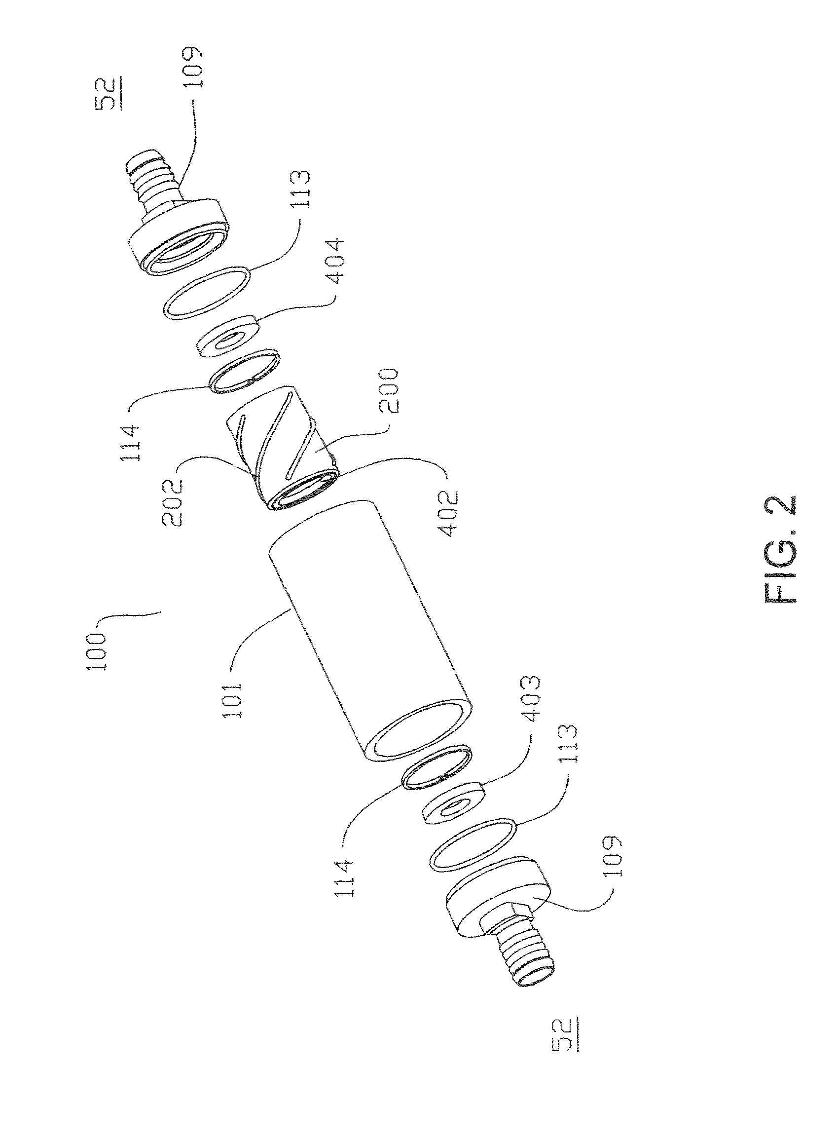
[0048]The invention, the pump / generator over-unity apparatus and method, is a serial array of electric generator turbine devices, each of which may act as a liquid or gas pump and an electric power generator, by providing magnets in ...


PUM


Abstract

The pump / generator apparatus and method provides a series of pump / generator devices, having magnets in place of conventional bearings, to generate electrical energy, creating a pump / generator for flowing liquids or gases. Stator coils on the outside of the housing gather electric current. The apparatus requires initial input power from an external power source to start the pumping and provides an initial external reservoir of liquid or gas flowing into the apparatus. A hollow turbine housing receiving flowing gas or liquid, encloses a freely spinning hollow drive cylinder. A helicoidal impeller gives the drive cylinder thrust to spin. Ring magnets vertically support the helicoidal impeller allowing the drive cylinder to float freely in the pipeline. Stator coils wind around and ring the exterior side of the housing to generate electric current.

Description

FIELD OF THE INVENTION[0001]This invention relates to pumps and generator devices which are compact and low maintenance, moving either liquid matter or gas matter. The invention is an apparatus comprising a series of pump / generators with low maintenance, higher flow rates, which are lighter and more compact without bearings which would cause contamination from bearing grease or debris. The apparatus provides a series of pump / generator devices having magnets in place of conventional bearings, bushings or axles to generate electrical energy from the spinning of the magnets within the apparatus, creating a pump / generator with high flow rates, for either liquids or gases. At the same time, stator coils are provided on the outside of the housing to the invention with which to gather electric current. The apparatus requires a small amount of initial input power from an external power source to start the pumping means and provides an initial external reservoir of matter (liquid or gas) flo...

Claims


Application Information

Patent Timeline
Patent Type & Authority Patents(United States)
IPC IPC(8): F03B13/00F03B13/10H02P9/04H02K7/18F01D15/10F03B17/00
CPCH02K7/1823F01D15/10F03B13/10Y10S415/916F03B17/005F03B3/103F05B2210/16F05B2220/20F05B2220/60F05B2240/51F16C32/0427Y02B10/50Y02E10/20
Inventor BURNS, III, GORDON CHARLESPARFITT, DAVID ALANFOLEY, JASON CHARLES
Owner BURNS III GORDON CHARLES
Features
  • R&D
  • Intellectual Property
  • Life Sciences
  • Materials
  • Tech Scout
  • Unparalleled Data Quality
  • Higher Quality Content
  • 60% Fewer Hallucinations
Learn More