Solid light source lighting device, illumination apparatus, and illumination system

a lighting device and light source technology, applied in the direction of electric lighting sources, electroluminescent light sources, semiconductor lamp usage, etc., can solve the problem of restricted dimming ratio of the lower limit, and achieve the effect of increasing the dimming ratio and shortening the response time period of actual optical outpu

Inactive Publication Date: 2015-10-20
PANASONIC INTELLECTUAL PROPERTY MANAGEMENT CO LTD
View PDF18 Cites 3 Cited by
  • Summary
  • Abstract
  • Description
  • Claims
  • Application Information

AI Technical Summary

Benefits of technology

[0023]The present invention has been made in view of the above-described problems, and an object of the present invention is to provide a solid light source lighting device, an illumination apparatus, and an illumination system, in which it is possible to shorten the response time period of actual optical output when a dimming control is performed so that a dimming ratio increases.
[0031]As described above, according to the present invention, it is possible to shorten the response time period of actual optical output when the dimming control is performed so that the dimming ratio increases.

Problems solved by technology

The conventional solid light source lighting device shown in FIG. 10 had the following problem when the forward voltage of the solid light source 100 is too high, or when the capacity of the capacitor C102 is too large.
That is, there is a possibility that the dimming ratio of the dimming lower limit is restricted depending on the maximum of the permissible response time period.

Method used


Image

  • Solid light source lighting device, illumination apparatus, and illumination system
  • Solid light source lighting device, illumination apparatus, and illumination system
  • Solid light source lighting device, illumination apparatus, and illumination system

Examples


first embodiment

[0046](First Embodiment)

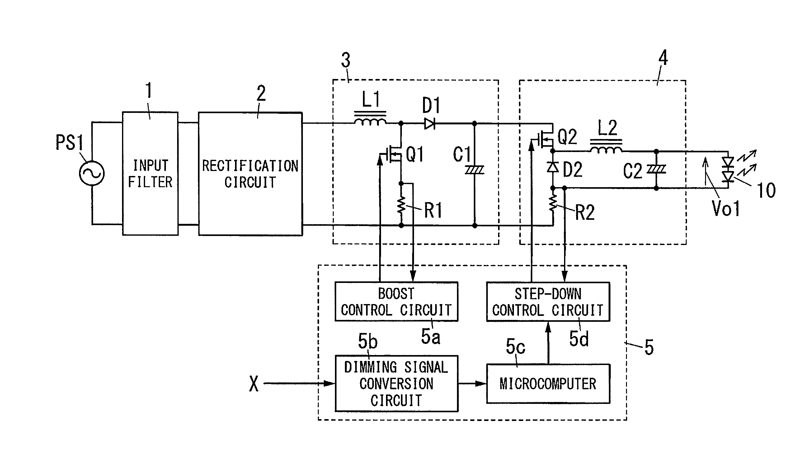
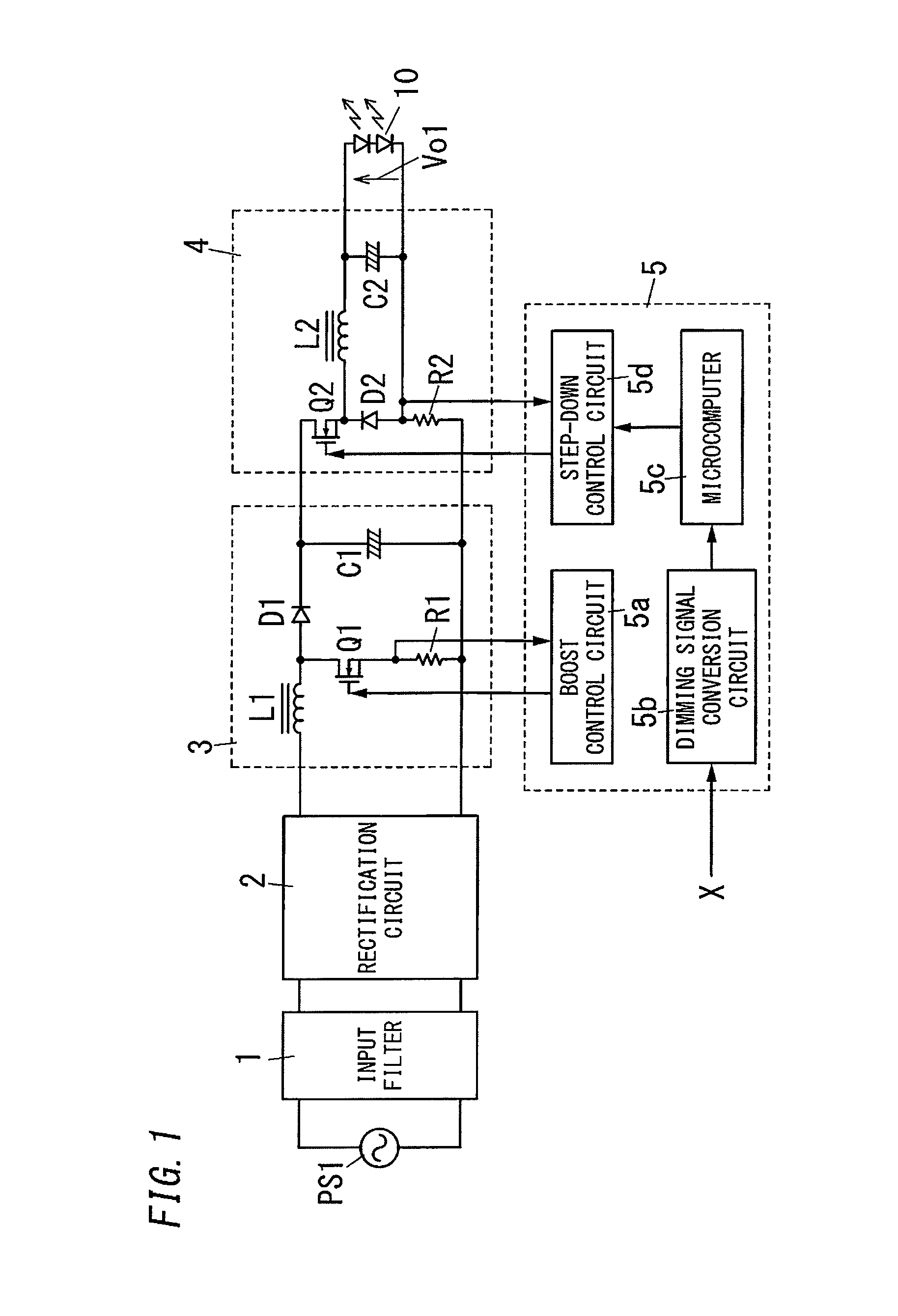
[0047]As shown in FIG. 1, the solid light source lighting device according to the present embodiment includes an input filter 1, a rectification circuit 2, a boost chopper circuit 3, a step-down chopper circuit 4, and a control circuit 5. The step-down chopper circuit 4 is equivalent to a power supply circuit of the present invention.

[0048]The input filter 1 is configured to remove unnecessary frequency components, such as a noise, in a state where a commercial power supply PS1 is used as an input power supply.

[0049]The rectification circuit 2 is configured to output a rectified voltage generated by performing rectification (full wave rectification, half-wave rectification) of an AC voltage inputted via the input filter 1.

[0050]The boost chopper circuit 3 includes a series circuit of an inductor L1 and a diode D1 that are connected to the high potential side of the rectified voltage. A series circuit of a switching element Q1 and a resistor R1 is connected be...

second embodiment

[0085](Second Embodiment)

[0086]As shown in FIG. 5, the solid light source lighting device according to the present embodiment includes a voltage detection circuit 6. Other configuration elements according to the present embodiment are the same as those of the first embodiment, the same configuration elements are assigned with same reference numerals, and explanation thereof will be omitted.

[0087]The voltage detection circuit 6 includes a series circuit of resistors R3 and R4 connected between the high voltage side of the capacitor C2 and the ground potential. A connecting point of the resistors R3 and R4 is connected to the A / D conversion port of the microcomputer 5c of the control circuit 5. That is, the detection value of the voltage across the solid light source 10 (output voltage Vo1) is inputted into the microcomputer 5c, and the microcomputer 5c is capable of obtaining the output voltage Vo1.

[0088]The dimming operation of this solid light source lighting device will be describ...

third embodiment

[0112](Third Embodiment)

[0113]In the solid light source lighting device according to the present embodiment, the microcomputer 5c is configured to perform the following operations with a storage part, such as EEPROM (Electrically Erasable Programmable Read-Only Memory) or a flash memory. The storage part, such as the EEPROM or the flash memory, may be built in the microcomputer 5c, provided outside the microcomputer 5c. For example, when R8C / 28 and 29 groups of Renesas Electronics Corporation are used as the microcomputer 5c, the flash memory is built in the microcomputer.

[0114]When an electrolytic condenser is used as the capacitor C2, the capacity of the capacitor C2 decreases as an accumulated lighting time period (energization time period) increases. That is, in this case, the capacity of the capacitor C2 decreases as the accumulated lighting time period is close to life time period. The accumulated lighting time period is an accumulated time period when a current flows thorough...


PUM


Abstract

A solid light source lighting device includes: a step-down chopper circuit including a switching element and outputting a DC power by turning on and off the switching element; a capacitor connected in parallel to a solid light source connected across output terminals of the step-down chopper circuit; and a control circuit determining a control value for a switching operation of the switching element based on a dimming signal for indicating a dimming ratio of the solid light source, and performing switching control of the switching element based on the control value. When performing switching control of the switching element so that the dimming ratio becomes high based on the dimming signal indicating a first dimming ratio, the control circuit performs the switching control of the switching element based on the control value that becomes a second dimming ratio higher than the first dimming ratio for a prescribed time period.

Description

TECHNICAL FIELD[0001]The present invention relates to a solid light source lighting device, an illumination apparatus, and an illumination system that perform a dimming of a solid light source.BACKGROUND ART[0002]In recent years, there is a solid light source lighting device that performs a dimming of a solid light source using a LED (Light Emitting Diode) element, an organic EL (Electro Luminescence) device, or the like.[0003]Generally, the solid light source lighting device is configured to control current flowing through solid light sources by a switching circuit (step-down chopper circuit, flyback circuit, or the like), and determine an amount of current flowing to the solid light sources with a dimming signal from a dimming signal generator, and dim the solid light sources.[0004]For example, there is a conventional solid light source lighting device, which includes a input filter 101, a rectification circuit 102, a boost chopper circuit 103, a step-down chopper circuit 104, and...

Claims


Application Information

Patent Timeline
Patent Type & Authority Patents(United States)
IPC IPC(8): H05B33/08H05B44/00
CPCH05B33/0818H05B33/0896H05B33/0851H05B33/0815Y02B20/346H05B45/38H05B45/3725Y02B20/30H05B45/10H05B45/375H05B45/14H05B45/60
Inventor WATANABE, KOJIKUROKI, YOSHIFUMI
Owner PANASONIC INTELLECTUAL PROPERTY MANAGEMENT CO LTD
Why Eureka
Try Eureka