
Noise reduction method, device and system on the basis of touch detection of a capacitive screen

a capacitive screen and capacitive technology, applied in the field of capacitive screen touch detection, can solve the problems of affecting the user experience of the capacitive screen, inability to achieve the desired filtering effect, and longer time delay, so as to improve the filtering performance, noise reduction, and prolong the scanning time

Active Publication Date: 2015-10-27
FOCALTECH SYST LTD
View PDF15 Cites 4 Cited by
  • Summary
  • Abstract
  • Description
  • Claims
  • Application Information

AI Technical Summary

Benefits of technology

The present invention provides a method, device, and system for reducing noise on a capacitive screen by improving the filtering performance of a filter. This is achieved by using a continuous scanning process that provides a stable and continuous signal to the receiving terminal, overcoming the limitation of scanning time in prior art. The method includes an improved structure of the filter that works together with the noise reduction method to achieve an effective and reliable noise reduction effect.

Problems solved by technology

When the scanning waveform at the sending terminal is mixed with an interference signal such as an environmental noise, a RF noise or an impulse noise, the interference signal will be passed to the receiving terminal and affect the judgment of change in the amplitude of the signal at the receiving terminal, which leads to an inaccurate test result and affects the user experience of the capacitive screen.
However the filter may output stability data only after a period of time delay so as to achieve the function of filtering, and the narrower the bandwidth of the filter, the longer the time delay.
Therefore, the filter may not be able to achieve the desired filtering effect if the amount of the input signals is relatively little, thereby the reliability of the output signal is affected.
However, since the length of the scanning waveform and the length of the scanning frame are limited, extending the scanning time at the sending terminal is limited, and therefore, increasing the amount of the signals is also limited.
Moreover, since it is needed to control processes including the scanning and the demodulation simultaneously for increasing the number of the scan channels, there will be a problem that the design complexity of the sending terminal and the receiving terminal is increased.

Method used


Image

  • Noise reduction method, device and system on the basis of touch detection of a capacitive screen
  • Noise reduction method, device and system on the basis of touch detection of a capacitive screen
  • Noise reduction method, device and system on the basis of touch detection of a capacitive screen

Examples


Embodiment Construction

[0050]The technical solution according to the embodiments of the present invention will be described clearly and completely as follows in conjunction with the accompany drawings in the embodiments of the present invention. It is obvious that the described embodiments are only a part of embodiments according to the present invention rather than all of them. All other embodiments obtained by the skilled in the art based on the embodiments in the present invention without any creative work belong to the scope of protection of the present invention.

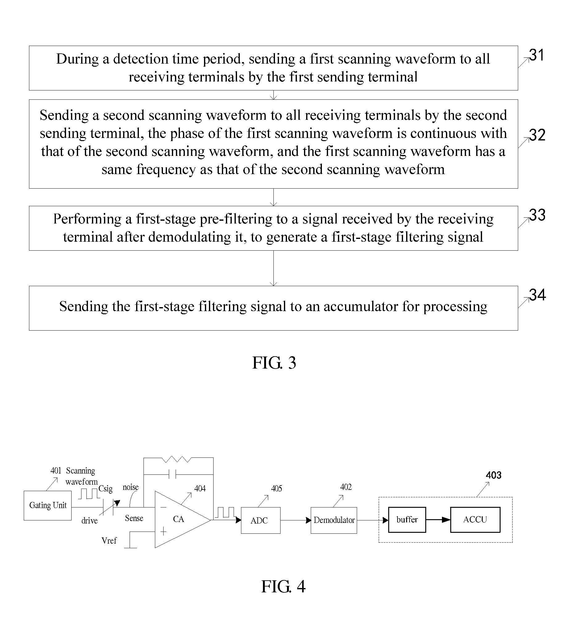
[0051]The embodiments of the present invention provides a noise reduction method, device and system on the basis of touch detection of a capacitive screen, so as to improve the filtering performance of a filter and thereby improve the noise reduction effect when a touch to a capacitive screen is detected, by improving a structure of the filter.

[0052]Before the explanation of the embodiments, it is needed to make clear that the noise reduction...


PUM


Abstract

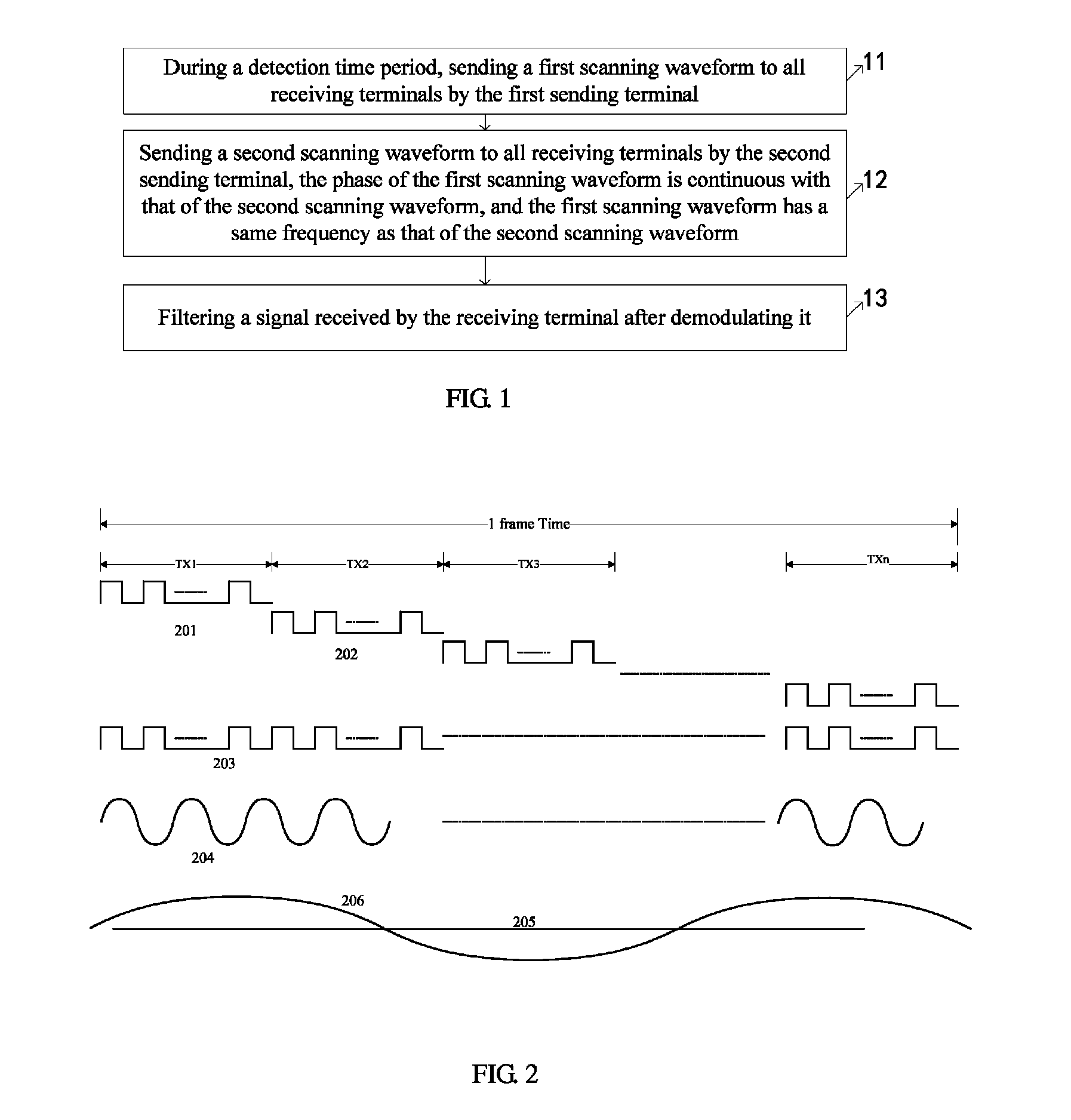
It is provided a noise reduction method, device and system on the basis of touch detection of a capacitive screen. The noise reduction method includes: sending a first scanning waveform to all receiving terminals by a first sending terminal and then sending a second scanning waveform to all the receiving terminals by a second sending terminal during a detection time period, wherein the phase of the first scanning waveform is continuous with that of the second scanning waveform and the first scanning waveform has a same frequency as that of the second scanning waveform; and filtering a signal received by the receiving terminals after demodulating it. Non-gap scanning can be achieved by performing continuation process to the scanning waveform, i.e. by achieving that the phases are continuous and the frequencies are the same.

Description

FIELD OF THE INVENTION[0001]The present invention generally relates to the technical field of touch detection for a capacitive screen, and in particular to a noise reduction method, device and system on the basis of touch detection of a capacitive screen.BACKGROUND OF THE INVENTION[0002]Capacitive screen is a mainstream screen at current stage, and is widely used in the field of mobile terminal such as a mobile phone or a tablet personal computer. The projected capacitive screen type of the capacitive screen includes a self-capacitance screen and a mutual-capacitance screen. Taking a mutual-capacitance screen as an example, the structure of the mutual-capacitance screen includes a number of sending terminals TXs and a number of receiving terminals RXs. When touch detection is performed to the mutual-capacitance screen or the mutual-capacitance is detected for obtaining its magnitude, a sending terminal sends a scanning waveform of a certain magnitude and frequency. The scanning wave...

Claims


Application Information

Patent Timeline
Patent Type & Authority Patents(United States)
IPC IPC(8): G06F3/045G06F3/044G06F3/041
CPCG06F3/0416G06F3/044G06F3/0418G06F3/04166G06F3/0443G06F3/0445G06F3/0446
Inventor MO, LIANGHUALI, CHENZHANG, JINGKAI
Owner FOCALTECH SYST LTD
Learn More