Device and method for the ablation of fibrin sheath formation on a venous catheter

a technology of fibrin sheath and catheter, which is applied in the field of devices and methods for the ablation of fibrin sheath formation on venous catheters, can solve the problems of fibrin sheath formation, unfavorable formation of fibrin sheath along the catheter wall, and plague essentially all central venous catheters

Active Publication Date: 2015-11-03
ANGIODYNAMICS INC
View PDF163 Cites 40 Cited by
  • Summary
  • Abstract
  • Description
  • Claims
  • Application Information

AI Technical Summary

Problems solved by technology

Notwithstanding the importance of venous catheters, one problem that is associated with their use is the undesired formation of fibrin sheaths along the catheter wall.
Fibrin sheath formation is an insidious problem that can plague essentially all central venous catheters.
Complete encasement of the catheter tip in a fibrin sheath may cause persistent withdrawal occlusion.
This can lead to extravasation of fluid where fluid enters the catheter to flow into the fibrin sheath, backtracks along the outside of the catheter, and exits out of the venous entry point and into the tissue.
The presence of a fibrin sheath on the catheter shaft may also result in difficulty removing the venous catheter, particularly PICC lines, from the patient.
Often patients who need prolonged intravenous regimens have compromised peripheral venous access and thus venous catheters are often the only means available for the delivery of necessary treatment.
However, mechanical disruption may not be effective because the fibrin sheath may not be completely removed and often causes damage to the catheter shaft and vessel wall.
Mechanical removal of fibrin build-up may also increase the risk of embolism due to free floating debris within the vessel.
Replacing the catheter is also an option, but this can cause increased trauma to the patient, increased procedure time and costs, increased risks of pulmonary emboli, and may require numerous attempts before removal is successful.
Thus, both mechanical disruption and catheter replacement may adversely affect a patient's dialysis schedule, cause patient discomfort, and loss of the original access site.
Drug therapies that address the fibrin sheaths can also result in complications and are unreliable.

Method used


Image

  • Device and method for the ablation of fibrin sheath formation on a venous catheter
  • Device and method for the ablation of fibrin sheath formation on a venous catheter
  • Device and method for the ablation of fibrin sheath formation on a venous catheter

Examples


Embodiment Construction

[0031]Electroporation is defined as a phenomenon that makes cell membranes permeable by exposing them to certain electric pulses. As a function of the electrical parameters, electroporation pulses can have two different effects on the permeability of the cell membrane. The permeabilization of the cell membrane can be reversible or irreversible as a function of the electrical parameters used. Reversible electroporation is the process by which the cellular membranes are made temporarily permeable. The cell membrane will reseal a certain time after the pulses cease, and the cell will survive. Reversible electroporation is most commonly used for the introduction of therapeutic or genetic material into the cell. Irreversible electroporation, also creates pores in the cell membrane but these pores do not reseal, resulting in cell death.

[0032]Irreversible electroporation has recently been discovered as a viable alternative for the ablation of undesired tissue. See, in particular, PCT Appli...


PUM


Abstract

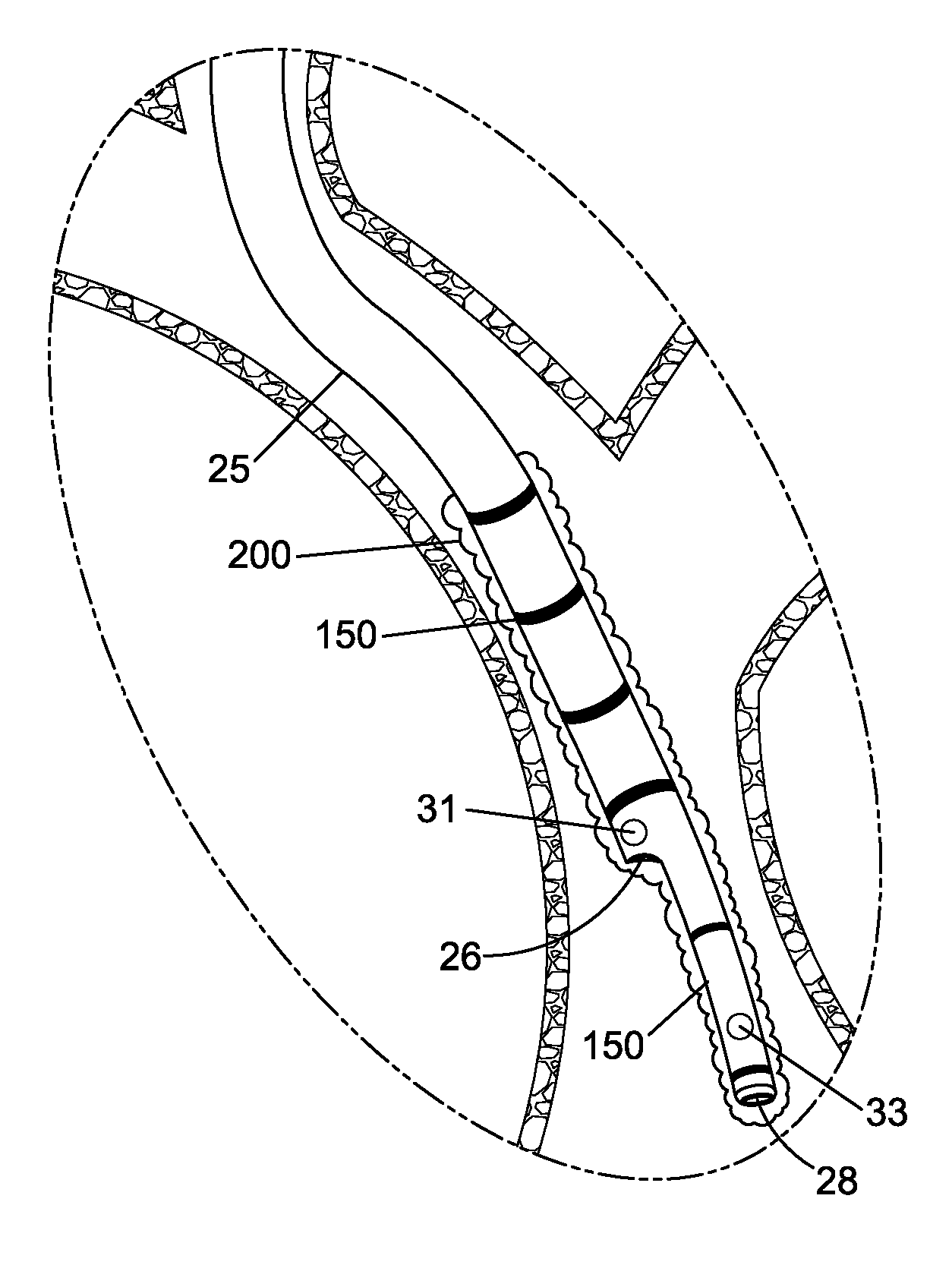
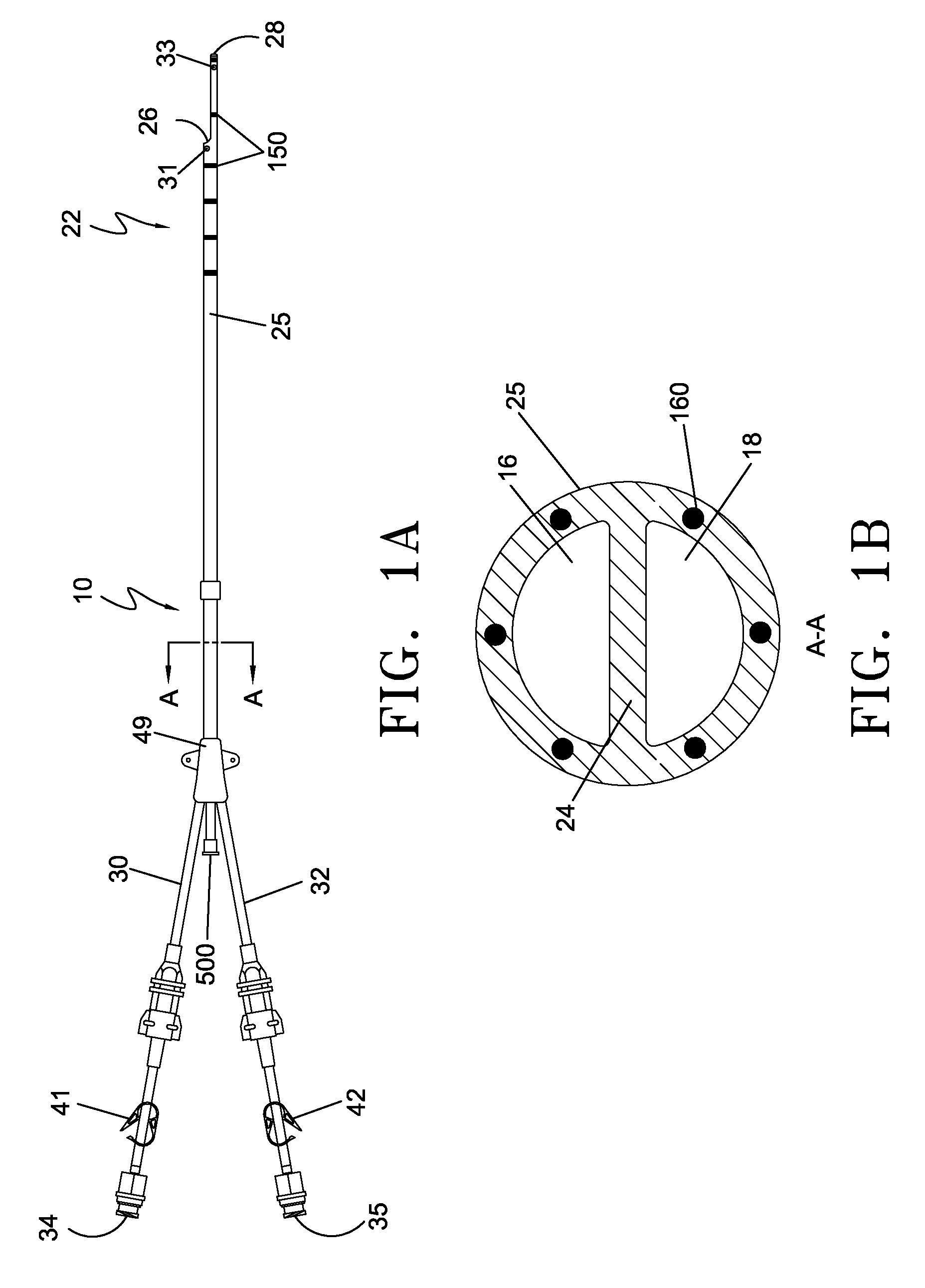
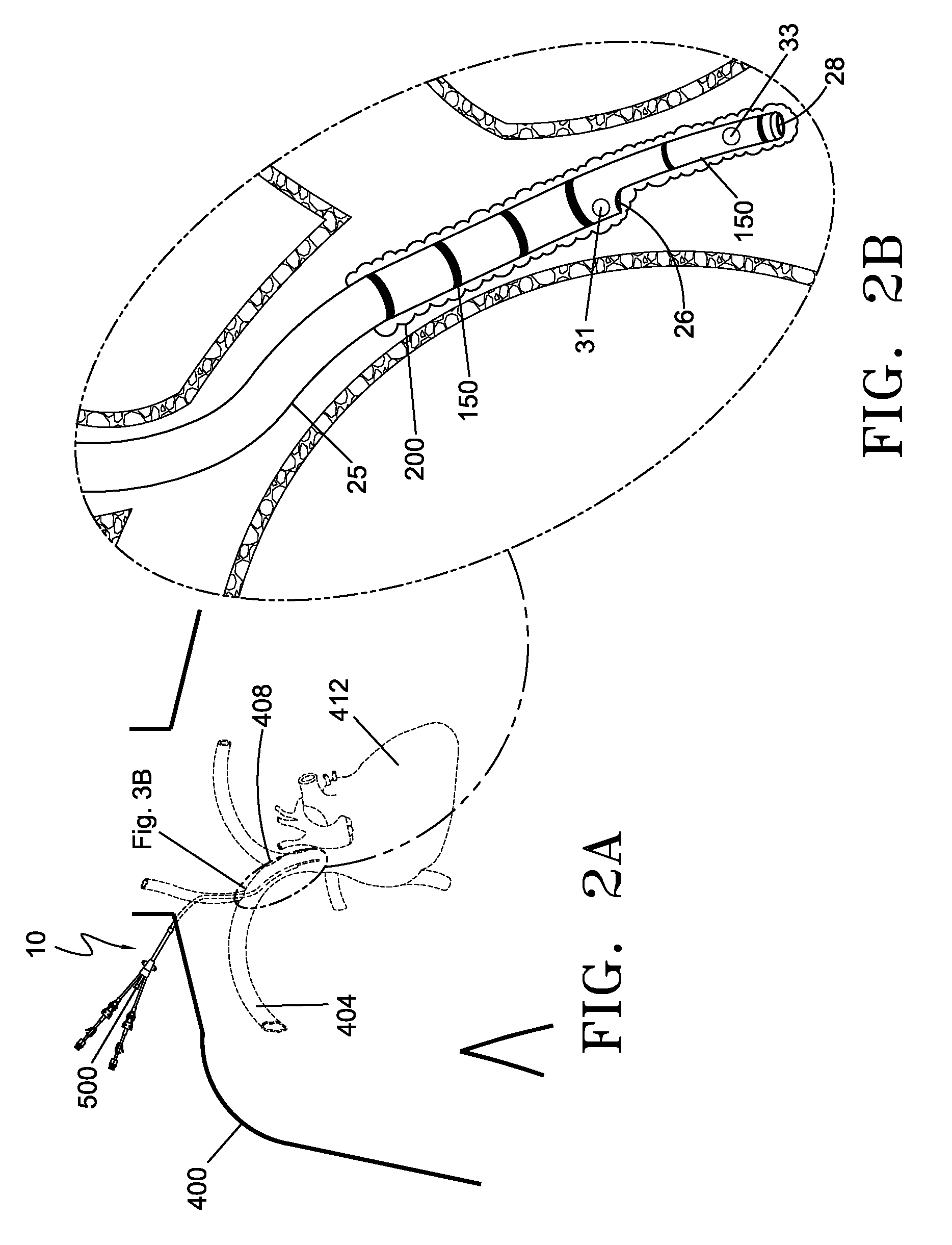
An indwelling venous catheter and method capable of destroying undesirable cellular growth is provided. The catheter includes a shaft having at least one lumen and adapted to be placed inside a vein for long term use. A plurality of electrodes are positioned near a distal section of the shaft and are adapted to receive from a voltage generator a plurality of electrical pulses in an amount sufficient to cause destruction of cells in the undesirable cellular growth that have grown around the shaft. In one aspect of the invention, a probe is configured to be removably insertable into the at least one lumen and the electrodes are positioned near the distal section of the probe.

Description

CROSS REFERENCE TO RELATED APPLICATIONS[0001]This application claims the benefit of priority under 35 U.S.C. Section 119(e) to U.S. Provisional Application Ser. No. 61 / 074,504, filed Jun. 20, 2008, entitled “Device And Method For The Ablation Of Fibrin Sheath Formation On A Venous Catheter Using Electroporation”, which is fully incorporated by reference herein.FIELD OF THE INVENTION[0002]The present invention relates to a medical device and method for the destruction of undesirable cellular growth on a venous catheter, such as fibrin sheath formation and / or infectious cells, by delivering a plurality of electrical pulses.BACKGROUND OF THE INVENTION[0003]Catheters, and more particularly, venous access catheters have many very important medical applications. For example, if a patient requires long-term dialysis therapy, a venous access catheter, such as a chronic dialysis catheter, will be implanted in a patient's body. Chronic dialysis catheters typically contain a polyester cuff tha...

Claims


Application Information

Patent Timeline
Patent Type & Authority Patents(United States)
IPC IPC(8): A61B18/12A61N1/32A61B18/14A61B18/00
CPCA61B18/1492A61N1/327A61B2018/0097A61B2018/00357A61B2018/00386A61B2018/00613A61B2018/00839A61M25/0043A61M2025/0019A61M2205/054
Inventor HOBBS, EAMONN P.HAMILTON, JR., WILLIAM C.
Owner ANGIODYNAMICS INC
Why Eureka
Try Eureka