Cooling device for engine
a cooling device and engine technology, applied in the direction of machines/engines, mechanical equipment, engine revolutions, etc., can solve the problems of increasing the cost of the device, poor startability, high fuel consumption, etc., and achieve the effect of improving the fuel consumption rate in the initial phase, efficient operation, and fine cooling control
- Summary
- Abstract
- Description
- Claims
- Application Information
AI Technical Summary
Benefits of technology
Problems solved by technology
Method used
Image
Examples
embodiment 1
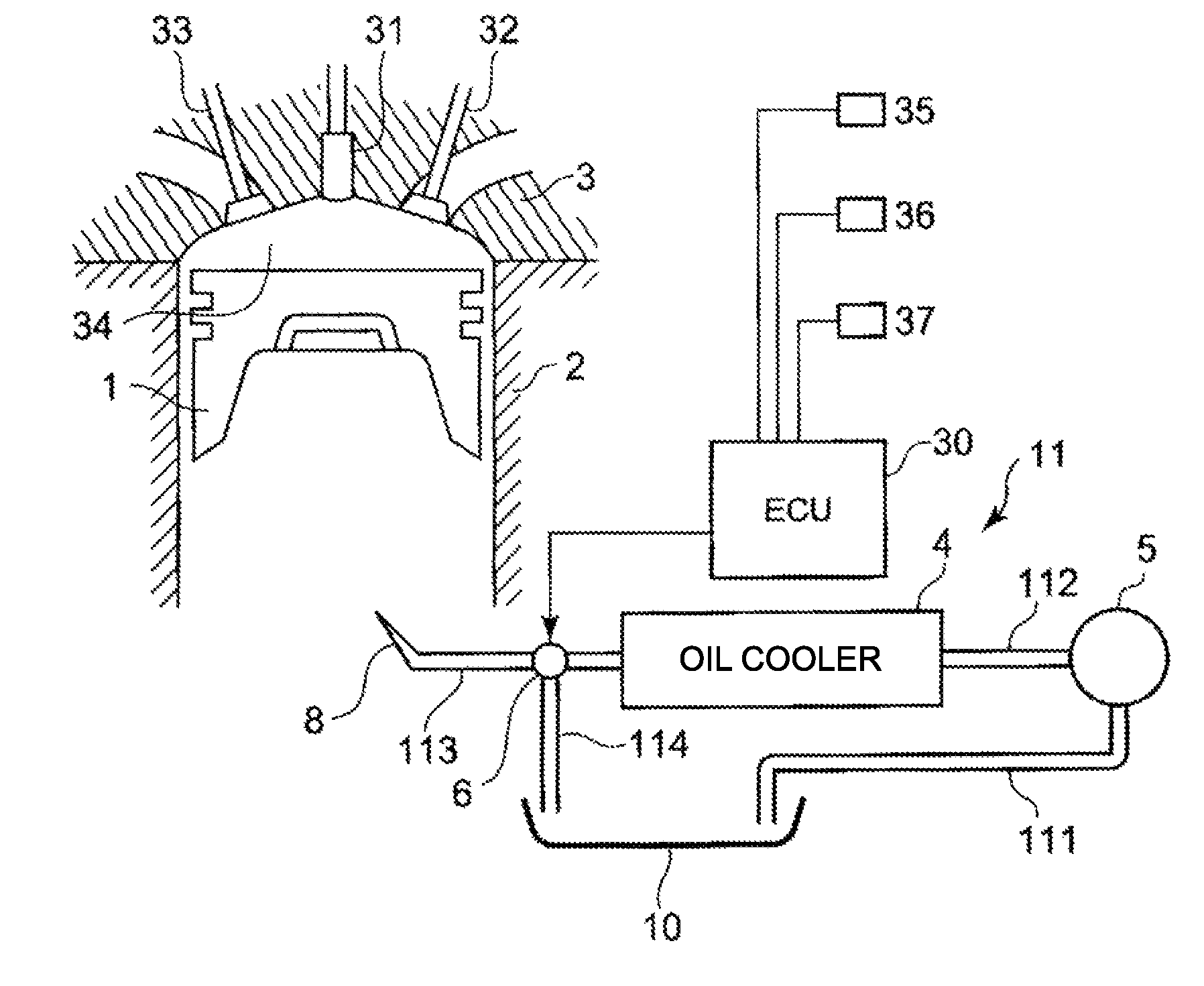
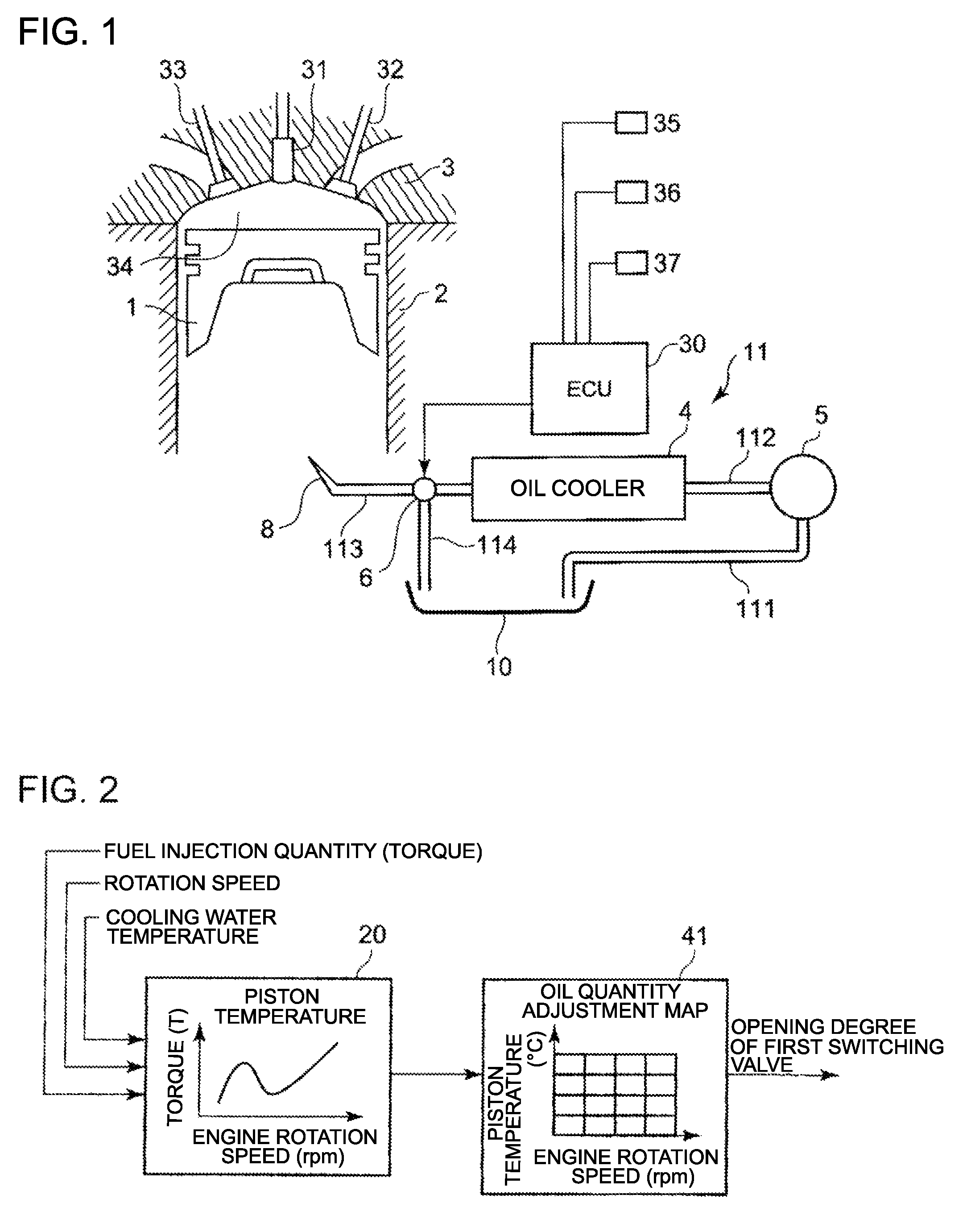
[0033]FIG. 1 shows a piston 1 which vertically slides in a cylinder 2 formed in an engine main unit.
[0034]A cylinder head 3 is installed in an upper part of the piston 1 so as to close the cylinder 2. In the cylinder head 3, a fuel injection nozzle 31 that injects fuel into a combustion chamber 34, an inlet valve 32 that introduces air into the cylinder, and an exhaust valve 33 that exhausts combustion gas are installed.
[0035]An oil injection unit (oil injection nozzle) 8 is secured in the engine main unit (not illustrated) facing the rear face of the piston 1 in the lower part of the piston 1.
[0036]5 denotes an oil pump which is connected to a crankshaft (not illustrated) of the engine via a gear train, and is driven simultaneously with the start of the engine, to draw up cooling oil from an oil pan 10 of the engine.
[0037]An oil cooler 4 is normally installed on the side of the engine main unit, and cools the cooling oil using the cooling water of the engine.
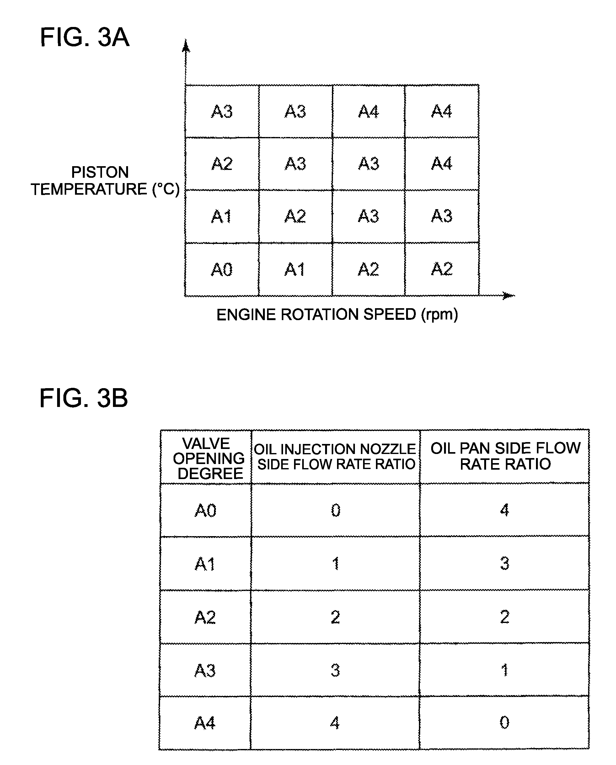
[0038]6 denotes a first...
embodiment 2
[0055]An engine cooling device according to Embodiment 2 will be described with reference to the schematic block diagram shown in FIG. 4.
[0056]A composing element the same as in Embodiment 1 is denoted with a same reference symbol, for which description is omitted.
[0057]In a distribution path 12, the cooling oil is drawn up from the oil pan 10 by the oil pump 5 via the first oil feed tube 111. A second switching adjustment valve 7 is inserted into the intermediate portion of the second oil feed tube 112 connecting an oil pump 5 and the oil cooler 4.
[0058]The third oil feed tube 113, which has the first switching adjustment valve 6 in the intermediation portion, is disposed at the downstream side of the distribution path 12 of the oil cooler 4.
[0059]The oil injection nozzle 8 is disposed further at the downstream side.
[0060]The first switching adjustment valve 6 is controlled (divides flow) based on an oil quantity adjustment map 41, which is disposed in the control unit 40, and dete...
embodiment 3
[0077]An engine cooling device according to Embodiment 3 will be described with reference to the schematic block diagram shown in FIG. 8.
[0078]A composing element the same as in Embodiment 1 or Embodiment 2 is denoted with a same reference symbol, for which description is omitted.
[0079]In the distribution path 12, the cooling oil is drawn up from the oil pan 10 by the oil pump 5 via the first oil feed tube 111. The second switching adjustment valve 7 is inserted into the second oil feed tube connecting the oil pump 5 and the oil cooler 4.
[0080]The third oil feed tube 113, which has the first switching adjustment valve 6 in the intermediate portion, is disposed in the downstream side of the distribution path 12 of the oil cooler 4, and the oil injection nozzle 8 is disposed further at the downstream side.
[0081]The second switching adjustment valve 7 is connected to the bypass circuit 9, of which one end is connected between the first switching adjustment valve 6 of the third oil feed...
PUM
 Abstract
Description
Claims
Application Information
 - R&D
- Intellectual Property
- Life Sciences
- Materials
- Tech Scout
- Unparalleled Data Quality
- Higher Quality Content
- 60% Fewer Hallucinations
Browse by: Latest US Patents, China's latest patents, Technical Efficacy Thesaurus, Application Domain, Technology Topic, Popular Technical Reports.
© 2025 PatSnap. All rights reserved.Legal|Privacy policy|Modern Slavery Act Transparency Statement|Sitemap|About US| Contact US: help@patsnap.com


