Check patentability & draft patents in minutes with Patsnap Eureka AI!

Electric power generation control device and electric power generation control system

a control device and power generation technology, applied in the direction of electric generator control, transportation and packaging, road transportation emission reduction, etc., can solve the problems of difficult to correctly perform the control of a generation amount of electric power, affecting the vibration suppression parameters which have a relatively high frequency, etc., and achieve the effect of high accuracy

Active Publication Date: 2015-11-10
DENSO CORP
View PDF27 Cites 4 Cited by
  • Summary
  • Abstract
  • Description
  • Claims
  • Application Information

AI Technical Summary

Benefits of technology

[0008]It is therefore desired to provide an electric power generation control device and an electric power generation control system, to be mounted to a motor vehicle equipped with an internal combustion engine, an alternator and a battery, capable of adjusting an electric power generation of the alternator driven by the internal combustion engine, of controlling the supply of the generated electric power to the battery and of suppressing vibration caused in the motor vehicle, with a simple structure.
[0012]The electric power generation control device having the structure and functions previously described does not directly control or adjust an output current outputted from the electric power generator, i.e. the alternator. That is, the electric power generation control device having the structure and functions previously described directly controls the exciting current flowing in the excitation winding of the electric power generator, i.e. the alternator on the basis of the charging parameters and the vibration suppression parameters. This makes it possible to correctly control the electric power supply from the electric power generator to the battery and suppress vibration of the motor vehicle with a simple structure.
[0015]The electric power generation control device having the structure and functions previously described can suppress the battery voltage from being affected by a high frequency component when a feedback control of the battery voltage is performed. This makes it possible to supply an optimum exciting current to the electric power generator, i.e. the alternator with high accuracy.

Problems solved by technology

That is, when a battery having a large electric resistance (charging / discharging resistance), which is generated during electric charging / discharging operation, is mounted to a motor vehicle, it becomes difficult to correctly perform a control of a generation amount of electric power by directly adjusting an output current of the alternator, as previously described, because a charging / discharging resistance is greatly changed according to an amount of a residual capacity (i.e. a residual charge) of the battery.
However, when the voltage of the battery is feedback to the charging parameters, there is a possibility of it being affected by the vibration suppression parameters which have a relatively high frequency.

Method used


Image

  • Electric power generation control device and electric power generation control system
  • Electric power generation control device and electric power generation control system
  • Electric power generation control device and electric power generation control system

Examples


first exemplary embodiment

[0031]A description will be given of an electric power generation control system 1 according to a first exemplary embodiment with reference to FIG. 1 to FIG. 8.

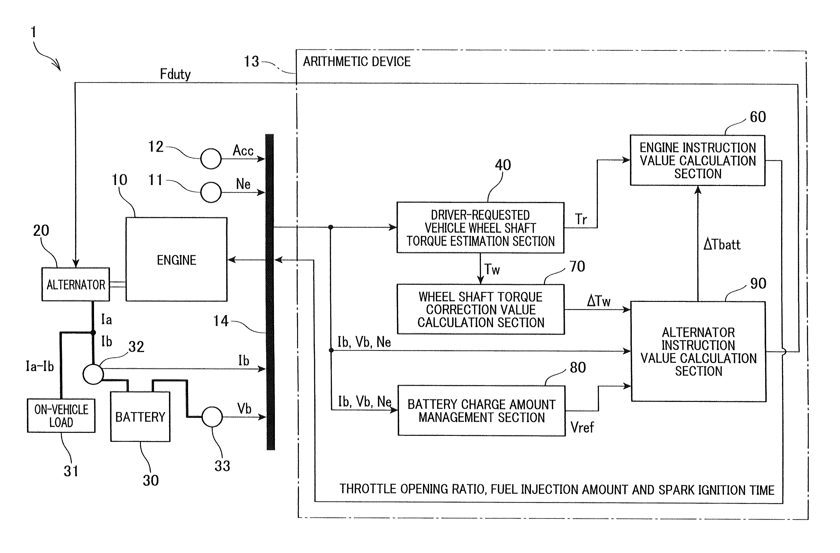
[0032]FIG. 1 is a view showing a block diagram showing a structure of the electric power generation control system 1, to be amounted to a motor vehicle, according to the first exemplary embodiment. As shown in FIG. 1, the electric power generation control system 1 is comprised of a spark ignition engine 10 (hereinafter, the engine 10), an alternator 20, an in-vehicle battery 30 (hereinafter, the battery 30), and an arithmetic device 13. The arithmetic device 13 works as the electric power generation control device.

[0033]The ECU 13 is equipped with a computer comprised of a central processing unit (CPU), a read only memory (ROM), a random access memory (RAM), etc. On performing a spark ignition of the engine 10, the ECU 13 calculates engine instruction values such as a spark ignition timing, a fuel injection amount, and an ope...

second exemplary embodiment

[0099]A description will now be given of the electric power generation control system according to a second exemplary embodiment with reference to FIG. 9 and FIG. 10.

[0100]The following description will explain a difference between the second exemplary embodiment and the first exemplary embodiment, and the same components between the second exemplary embodiment and the first exemplary embodiment will be referred with the same reference numbers and characters for brevity.

[0101]FIG. 9 is a view showing a block diagram of the alternator instruction value calculation section 90 as the function of the arithmetic device 13 according to the second exemplary embodiment.

[0102]FIG. 10 is a view showing a flow chart of a process of calculating alternator instruction values performed by the arithmetic device 13 as the alternator instruction value calculation section 90 according to the second exemplary embodiment shown in FIG. 9.

[0103]Like the process in the first exemplary embodiment previousl...

third exemplary embodiment

[0115]A description will now be given of the electric power generation control system according to a third exemplary embodiment with reference to FIG. 11, FIG. 12 and FIG. 13.

[0116]FIG. 11 is a view showing a block diagram of functions of the alternator instruction value calculation section in the arithmetic device 13 according to the third exemplary embodiment. FIG. 12 is a view showing a flow chart of a process of calculating alternator instruction values performed by the arithmetic device 13 which works as the alternator instruction value calculation section 90 according to the third exemplary embodiment shown in FIG. 11.

[0117]The alternator instruction value calculation section 90 according to the third exemplary embodiment performs the alternator instruction value calculation process shown in FIG. 12 in a case when it is possible to determine the upper limit of the duty ratio Fduty of the exciting current outputted from the voltage regulator 904, but not possible to directly de...


PUM


Abstract

An ECU in an electric power generation control system obtains a vehicle state containing a battery state and a driving state of a motor vehicle. The ECU calculates charging parameters necessary for maintaining a residual charge of a battery and vibration suppression parameters necessary for suppressing vibration of a vehicle. An exciting current setting section as a function of the ECU determines an exciting current flowing in an excitation winding of an alternator on the basis of the charging parameters and the vibration suppression parameters.

Description

CROSS-REFERENCE TO RELATED APPLICATION[0001]This application is related to and claims priority from Japanese Patent Application No. 2012-287521 filed on Dec. 28, 2012, the contents of which are hereby incorporated by reference.BACKGROUND OF THE INVENTION[0002]1. Field of the Invention[0003]The present invention relates to electric power generation devices and systems, mounted on motor vehicles comprised of internal combustion engines, which control a generation of electric power by an alternator driven by an internal combustion engine and a supply of the generated electric power to a battery.[0004]2. Description of the Related Art[0005]There is a known device regarding such a type of the electric power generation control devices. For example, a patent document, Japanese patent No. JP 4483985, has disclosed a device to adjust a driving torque of an alternator to suppress various vibrations of a motor vehicle. In general, various types of vibrations are caused in a motor vehicle, for ...

Claims


Application Information

Patent Timeline
Patent Type & Authority Patents(United States)
IPC IPC(8): H02P9/04B60W30/20H02J7/14B60W10/06B60W10/30B60W50/00
CPCH02P9/04B60W10/06B60W10/30B60W30/20H02J7/1446B60W2030/206B60W2050/0056B60W2510/244B60W2710/083B60W2710/244Y02T10/92B60W2710/086B60W2050/0052
Inventor MINAMIGUCHI, YUUICHIOOKAWA, ISAOMORI, KATSUYUKIYAGYU, AKIHIKO
Owner DENSO CORP
Features
  • R&D
  • Intellectual Property
  • Life Sciences
  • Materials
  • Tech Scout
  • Unparalleled Data Quality
  • Higher Quality Content
  • 60% Fewer Hallucinations
Learn More