
Method and apparatus for heating a pre-coated plate of steel

a pre-coated plate and pre-coating technology, which is applied in the direction of heat treatment apparatus, manufacturing tools, furnaces, etc., can solve the problems of inability to fully develop the oxide layer, limited formation of the desired oxide layer on the coating, and significant increase in wear, so as to facilitate a targeted change in the shape of the semi-finished product, reduce the strength of the used material, and reduce the effect of ductility

Active Publication Date: 2015-11-24
BENTELER AUTOMOBILTECHNIK GMBH
View PDF23 Cites 8 Cited by
  • Summary
  • Abstract
  • Description
  • Claims
  • Application Information

AI Technical Summary

Benefits of technology

The present invention aims to reduce the negative effects of hydrogen embrittlement on steel plates during the forming process. It achieves this by decreasing the amount of water in the furnace atmosphere, which reduces the amount of hydrogen produced. By increasing the amount of oxygen in the atmosphere, an oxide layer is formed on the coating, which reduces adherence to the shaping zones of the forming tool and lessens abrasion to moving parts. This results in reduced maintenance works and saves on costs associated with the use of ceramic rollers in continuous furnaces.

Problems solved by technology

This causes not only stoppage and set-up and maintenance works, but a removal of hard deposits requires also grinding of the forming tool zones so that wear is significantly increased.
As the furnace atmosphere is heated, the contained oxygen proportion is decreased at least in some areas so that the formation of the desired oxide layer on the coating is limited.
As a result, the oxide layer is unable to fully develop in order to counteract the adherence of the coating on the forming tool so that added deposits are encountered.
In addition, as the aluminum oxide layer is not fully developed and partly detaches, dust is increasingly formed, causing increased wear through abrasion of the guided and / or bearing-mounted components of the forming tool.
Thus, guides of slides or brakes of the forming tool for example are subject to increased wear.
Water is broken down by thermal stress inside the furnace and leads to an increased proportion of hydrogen which can cause hydrogen embrittlement of the steel.
For economical reasons, the furnace is built with small openings for charging and discharging so that only a small fraction of atmospheric oxygen is able to migrate into the furnace and thus again the formation of an advantageous oxide layer on the coating is limited.

Method used


Image

  • Method and apparatus for heating a pre-coated plate of steel
  • Method and apparatus for heating a pre-coated plate of steel
  • Method and apparatus for heating a pre-coated plate of steel

Examples


Embodiment Construction

[0077]Throughout all the figures, same or corresponding elements may generally be indicated by same reference numerals. These depicted embodiments are to be understood as illustrative of the invention and not as limiting in any way. It should also be understood that the figures are not necessarily to scale and that the embodiments are sometimes illustrated by graphic symbols, phantom lines, diagrammatic representations and fragmentary views. In certain instances, details which are not necessary for an understanding of the present invention or which render other details difficult to perceive may have been omitted.

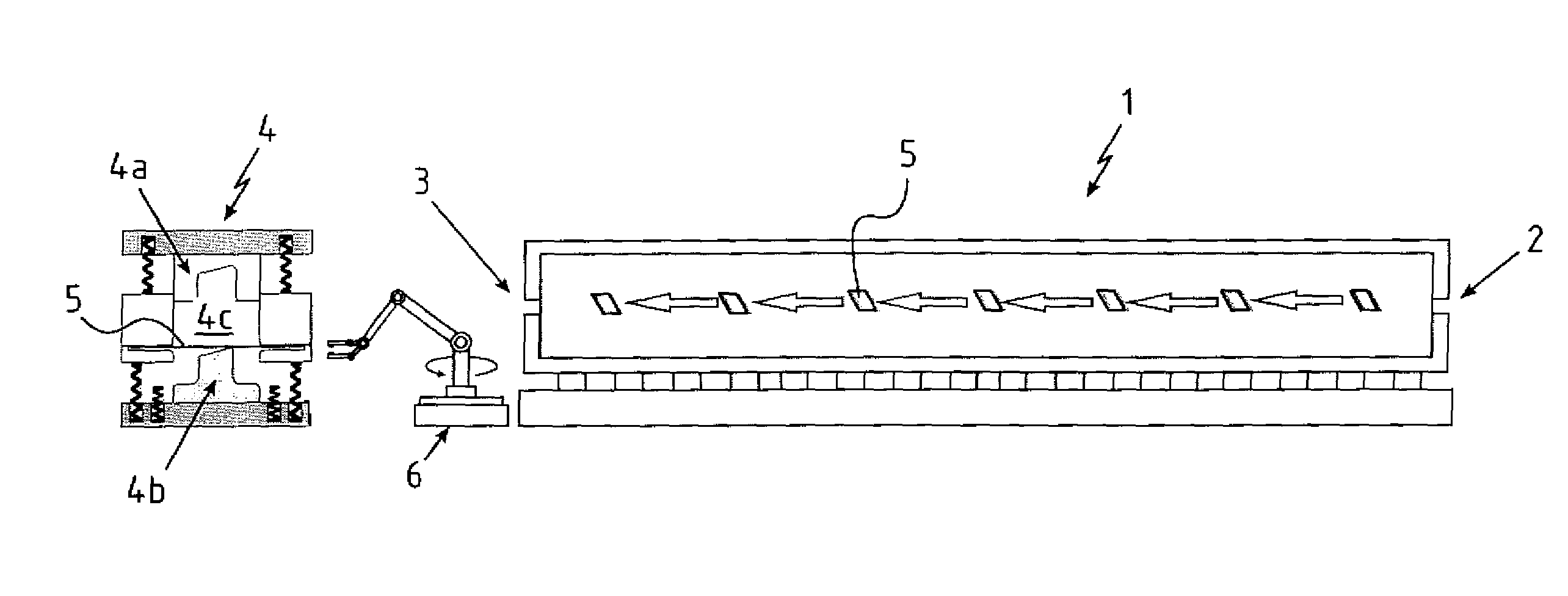
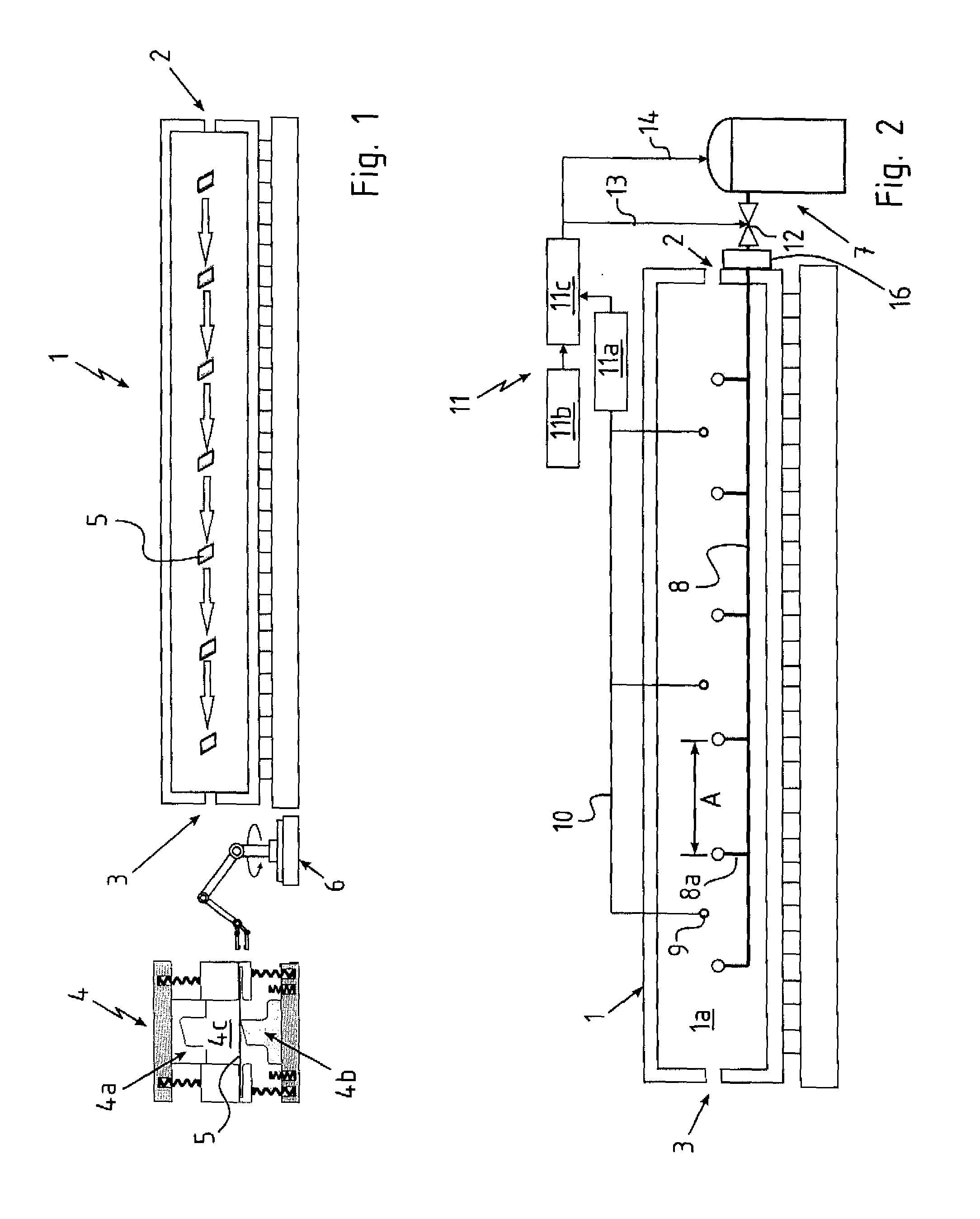
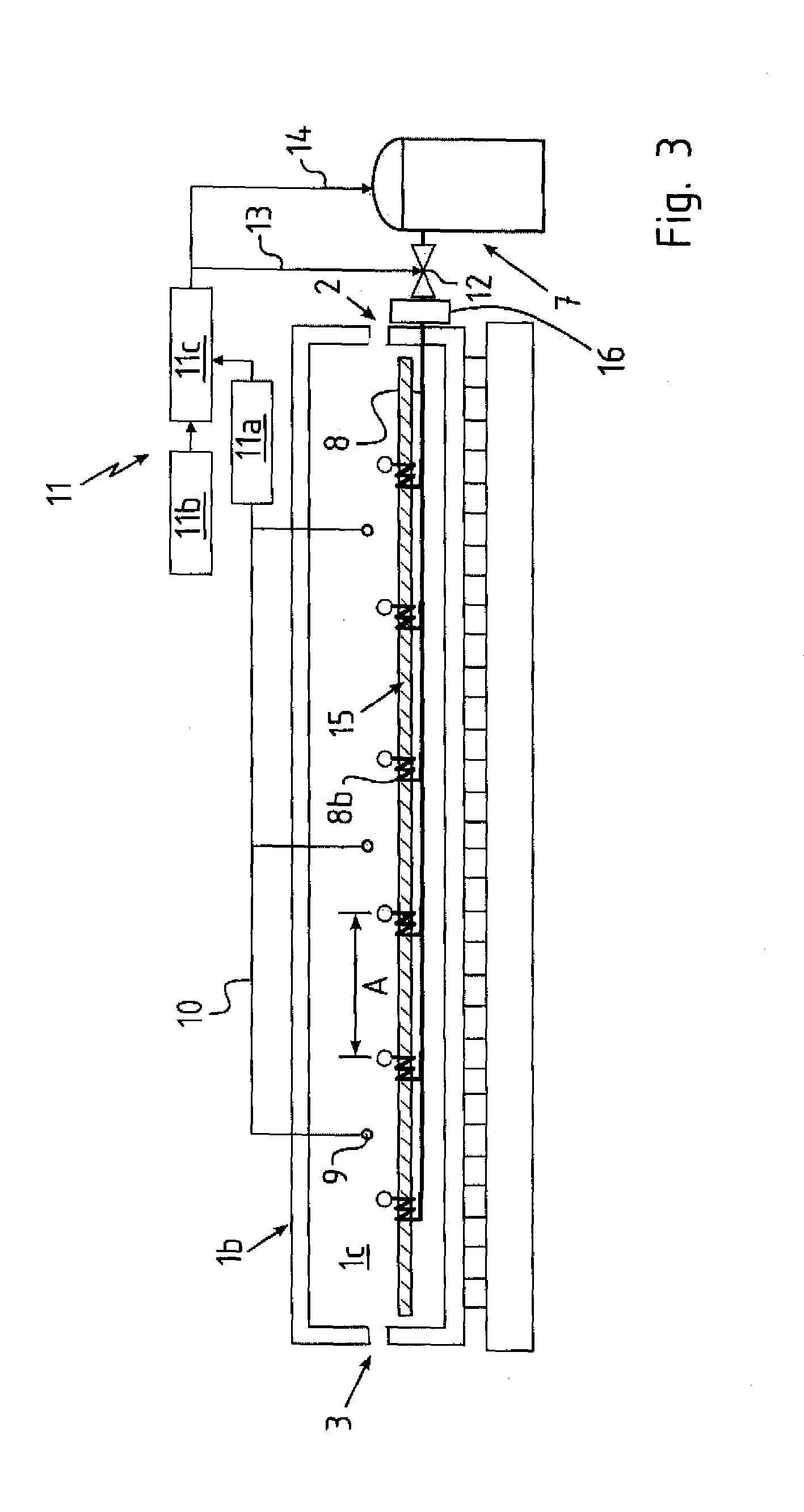
[0078]Turning now to the drawing, and in particular to FIG. 1, there is shown a side view of a furnace, generally designated by reference numeral 1 and configured in the form of a continuous furnace extending in a longitudinal direction. The furnace 1 has opposite ends, each formed with an opening, with the opening shown on the right-hand side of FIG. 1 representing an entra...


PUM

PropertyMeasurementUnit
temperatureaaaaaaaaaa
dew pointaaaaaaaaaa
dew pointaaaaaaaaaa

Abstract

A pre-coated plate of steel is heated in a furnace to form an intermetallic alloying layer on the plate at least in an area thereof. Air is pretreated through drying to produce dried air which is fed into the furnace to control the atmosphere within the furnace while the pre-coated plate is in the furnace.

Description

CROSS-REFERENCES TO RELATED APPLICATIONS[0001]This application claims the priority of German Patent Application, Serial No. 10 2011 053 634.5, filed Sep. 15, 2011, pursuant to 35 U.S.C. 119(a)-(d), the content of which is incorporated herein by reference in its entirety as if fully set forth herein.BACKGROUND OF THE INVENTION[0002]The present invention relates to a method and apparatus for heating a pre-coated plate of steel.[0003]The following discussion of related art is provided to assist the reader in understanding the advantages of the invention, and is not to be construed as an admission that this related art is prior art to this invention.[0004]Production of hot formed structural parts is based on plastic formation of mostly flat semi-finished products. Unlike cold forming at room temperature, the preceding heating of metallic semi-finished products in particular prevents the presence of unwanted solidification and decreased ductility in the forming zone. In addition, heating...

Claims


Application Information

Patent Timeline
Patent Type & Authority Patents(United States)
IPC IPC(8): C21D1/76C21D9/46C23C2/28C23C2/26C23C8/10C22C38/02C22C38/04C22C38/06C22C38/14C22C38/22C22C38/28C22C38/32C22C38/38C22C38/00
CPCC23C8/10C21D1/76C21D9/46C22C38/02C22C38/04C22C38/06C22C38/14C22C38/22C22C38/28C22C38/32C22C38/38C23C2/26C23C2/28C21D2241/00
Inventor STEINS, CHRISTOPHRODE, MATTHIASPELLMANN, MARKUSBAKE, KARSTENHIELSCHER, CHRISTIAN
Owner BENTELER AUTOMOBILTECHNIK GMBH
Learn More