
Field-ionization based electrical space ion thruster using a permeable substrate

a field-ionization and electrical space ion technology, applied in the field of space ion thrusters, can solve the problems of too large size and mass of the electron bombardment chamber required for ionization to occur, and achieve the effect of reducing the size and mass of the electron bombardment chamber for use in small satellites and cubesats

Active Publication Date: 2015-11-24
THE UNITED STATES OF AMERICA AS REPRESENTED BY THE SECRETARY OF THE NAVY
View PDF11 Cites 34 Cited by
  • Summary
  • Abstract
  • Description
  • Claims
  • Application Information

AI Technical Summary

Benefits of technology

The patent describes a type of electric ion propellant that produces a beam of ions using a process called field-ionization. The system includes a chamber that injects gas propellant into and a substrate that produces positive ions and freed electrons through field ionization. The positive ions are then accelerated and neutralized before being directed out of the chamber. The substrate can be infused with nano-materials to help bring about the production of positive ions. The system can be powered by an external circuit that transfers the freed electrons from the substrate to the neutralizer. This technology can improve the efficiency and performance of electric ion propellants in producing an ion beam for space applications.

Problems solved by technology

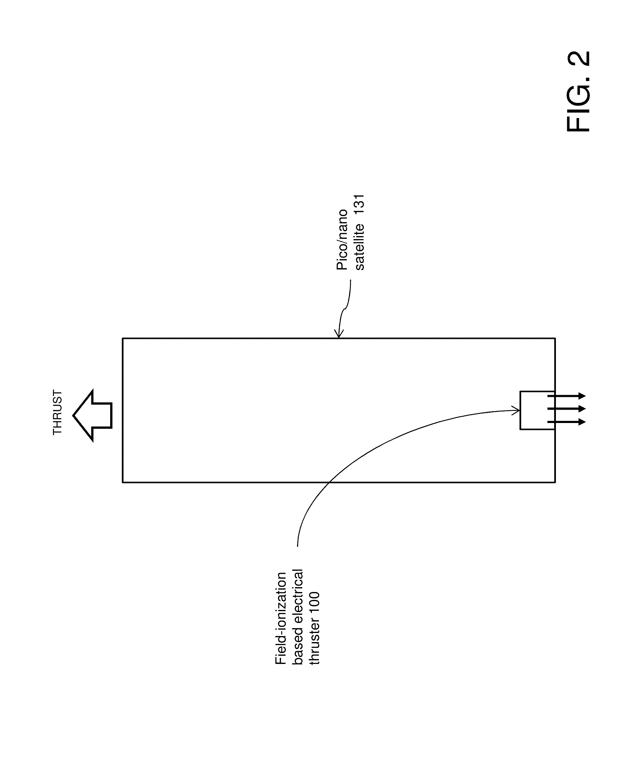
The small amount of propellant mass required to operate ion thrusters for such a long time also makes ion thrusters attractive for use in small satellites and CubeSats; however, the size and mass of the electron bombardment chamber required for ionization to occur is too large for use in small satellites and CubeSats.

Method used


Image

  • Field-ionization based electrical space ion thruster using a permeable substrate
  • Field-ionization based electrical space ion thruster using a permeable substrate
  • Field-ionization based electrical space ion thruster using a permeable substrate

Examples


Embodiment Construction

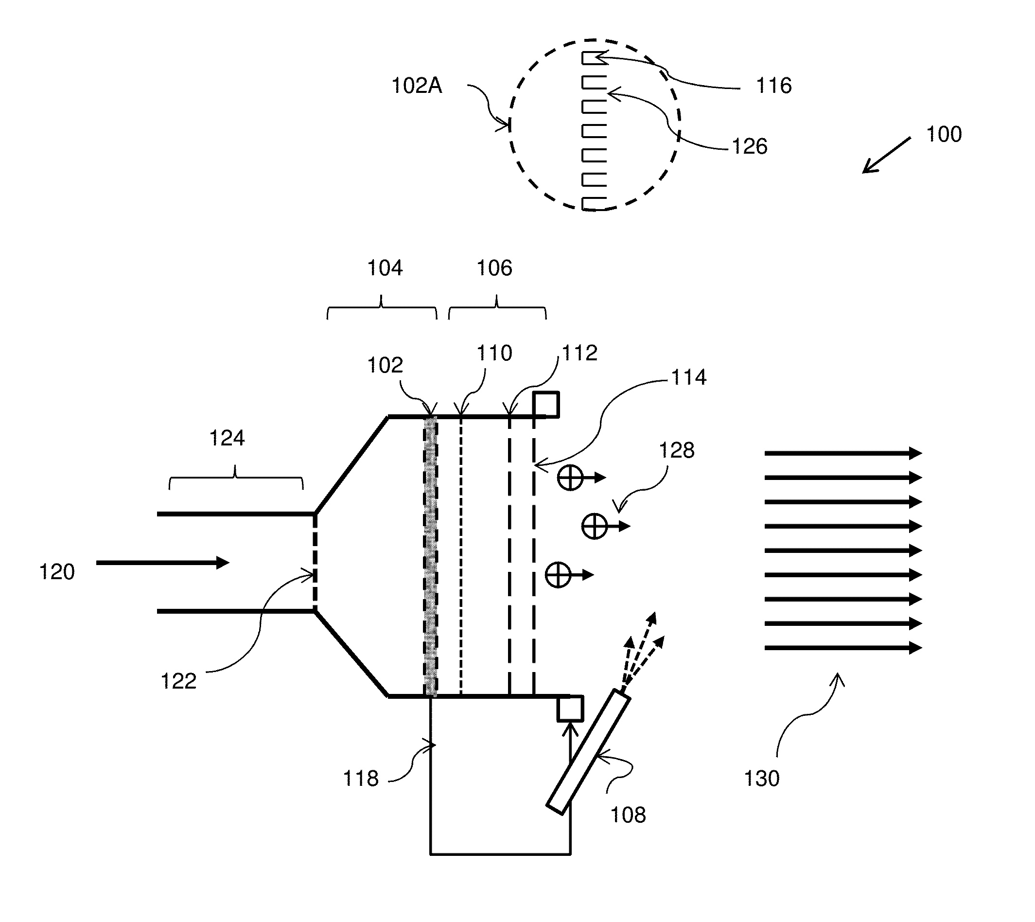
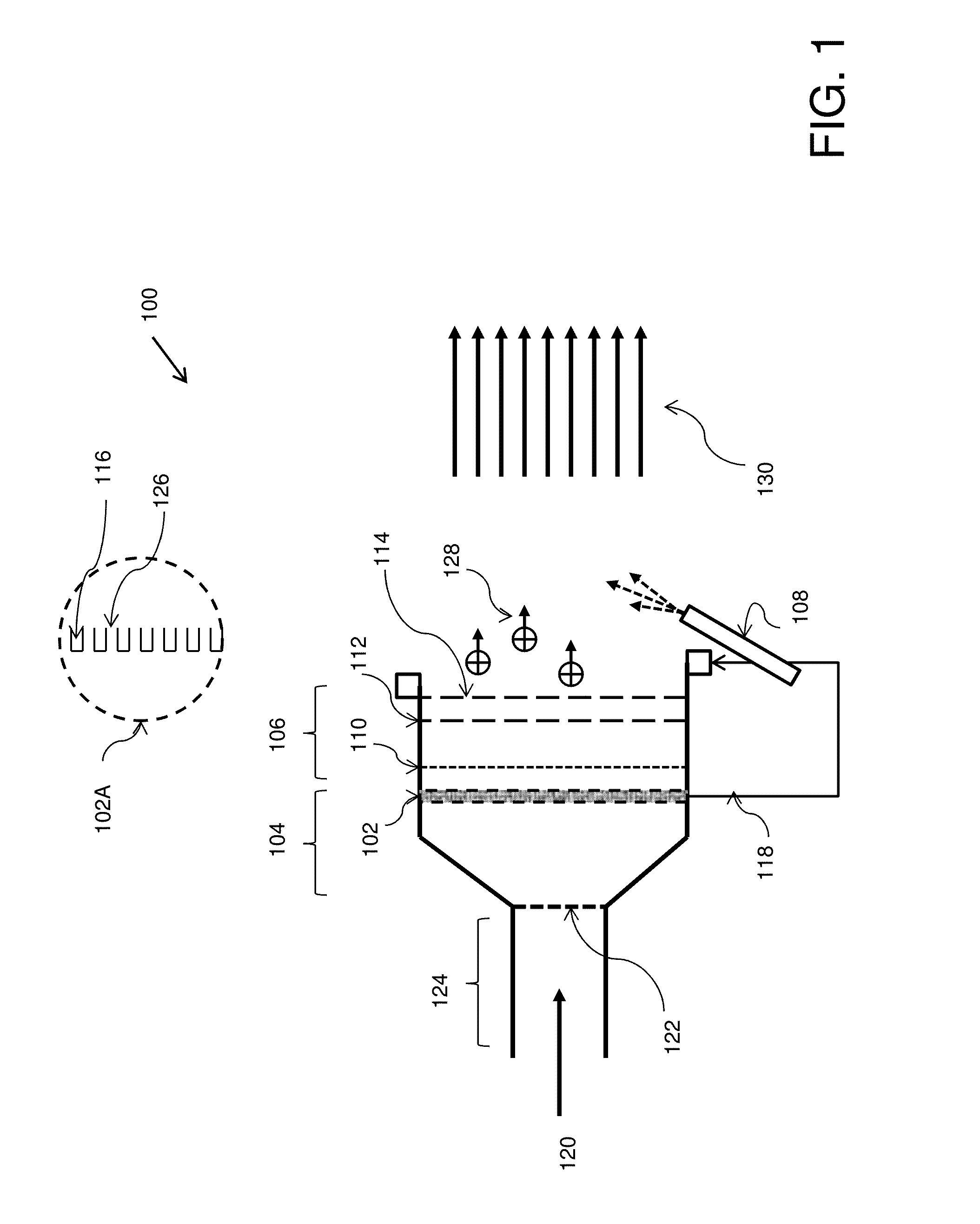
[0013]Broadly viewed, embodiments for small satellites and CubeSats provide a dual propulsion system using a single-propellant source that can be used in either a high specific impulse mode, also termed herein an ion-thruster mode, or a low specific impulse mode, also termed herein a cold-gas thruster mode. In one embodiment, the high specific impulse mode includes a miniaturized positive-ion field-ionization chamber which includes a permeable ionizer substrate, such as carbon nanotubes (CNTs) or other nano-materials, which is fed propellant from a porous injection matrix, i.e., a porous plug for flow control, made from permeable carbon or other permeable material. In one embodiment, field-electron emission from a neutralizer, such as a carbon nanotube array neutralizer, positioned downstream of accelerator grids is used for ion neutralization. In one embodiment, the low specific impulse mode uses a conventional supersonic nozzle-expansion to generate thrust. In one embodiment, both...


PUM


Abstract

A field-ionization based electrical ion thruster utilizes a single propellant that can be used in either a high specific-impulse mode, i.e., ion-thruster mode, or a low-specific-impulse mode, i.e., a cold-gas thruster mode. In one embodiment, the high specific impulse mode (ion thruster mode) utilizes a miniaturized positive-ion field-ionization chamber including a permeable substrate infused with properly oriented carbon nanotubes (CNTs), which is fed propellant from a porous injection plug made from permeable carbon or equivalent material. In one embodiment, field-electron emission from a neutralizer, such as a carbon nanotube array neutralizer, positioned after one or more accelerator grids is used for ion neutralization. In one embodiment, the low specific-impulse (cold-gas mode) uses a conventional supersonic nozzle-expansion to generate thrust. In one embodiment, both the high specific-impulse mode and the low specific-impulse mode thruster embodiments share the same gas propellant, storage propellant tank, and delivery equipment.

Description

CROSS-REFERENCE TO RELATED APPLICATIONS[0001]This application claims the benefit of U.S. Provisional Patent Application No. 61 / 303,059, filed Feb. 10, 2010, which is hereby incorporated in its entirety by reference.BACKGROUND OF THE INVENTION[0002]1. Field of the Invention[0003]The present invention relates generally to space ion thrusters.[0004]2. Description of the Related Art[0005]Ion thrusters have the capability to provide constant thrust with a high specific impulse for years. Thus ion thrusters have been utilized in spacecraft for long duration and inter-planetary missions. Current designs for ion thrusters use electron collision for propellant ionization.[0006]Electron collision ionization sources bombard a gas atom with electrons that are emitted from a heated cathode. As the electrons collide with the gas atoms, they knock off one or more electrons. A relatively large chamber with magnets or RF fields to increase the electron path is required to maximize ionization. The ne...

Claims


Application Information

Patent Timeline
Patent Type & Authority Patents(United States)
IPC IPC(8): F03H1/00F03H99/00B64G1/40
CPCF03H1/00F03H99/00F03H1/0012F03H1/0025B64G1/405H01J27/26F03H1/0037H01J2201/30469B64G1/413
Inventor BIBLARZ, OSCARROMANO, MARCELLO
Owner THE UNITED STATES OF AMERICA AS REPRESENTED BY THE SECRETARY OF THE NAVY
Learn More