Intervertebral implant for mutual situating of adjacent vertebrae

a technology of intervertebral implants and adjacent vertebrae, which is applied in the field of intervertebral implants for mutual positioning of adjacent vertebrae, can solve the problems of lack of opportunity to displace adjacent vertebrae relative to each other in the coronal or sagittal plane, and lack of mutual adjustment of vertebrae, etc., to achieve simple and compact construction, efficient performance, and restore normal adjustment of vertebrae

a technology of intervertebral implants and adjacent vertebrae, which is applied in the field of intervertebral implants for mutual positioning of adjacent vertebrae, can solve the problems of lack of opportunity to displace adjacent vertebrae relative to each other in the coronal or sagittal plane, and lack of mutual adjustment of vertebrae, etc., to achieve simple and compact construction, efficient performance, and restore normal adjustment of vertebrae

US9198771B2Inactive Publication Date: 2015-12-01LFC Z O O

Image

  • Intervertebral implant for mutual situating of adjacent vertebrae
  • Intervertebral implant for mutual situating of adjacent vertebrae
  • Intervertebral implant for mutual situating of adjacent vertebrae

Examples


Embodiment Construction

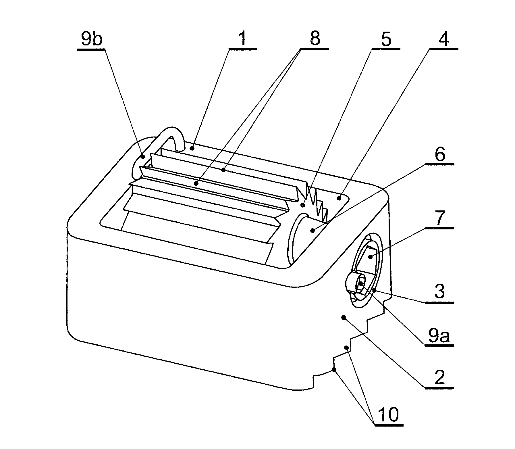
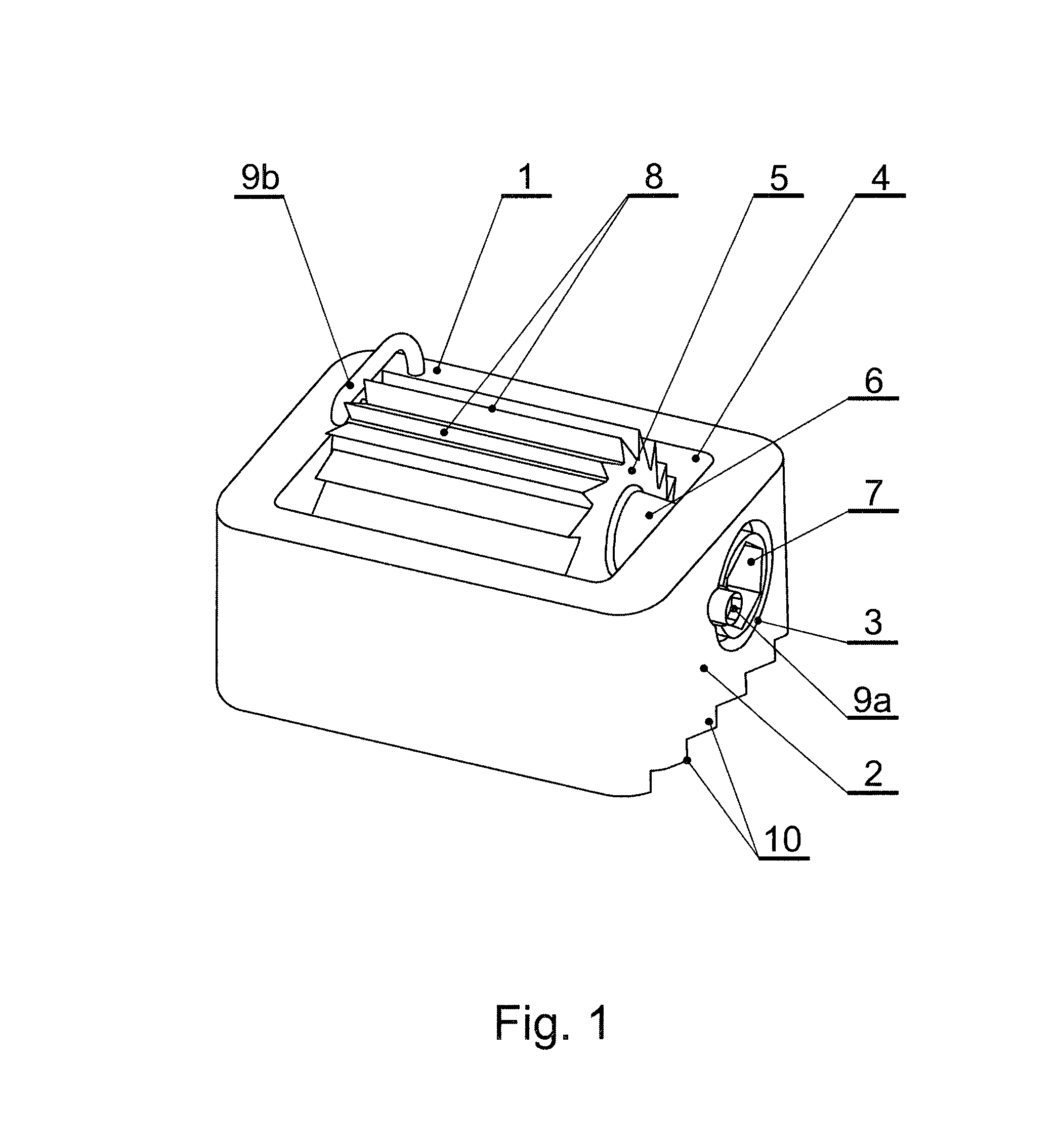
[0118]Presented on FIG. 1 intervertebral implant for mutual situating of adjacent vertebrae contains a cover 1 in a shape close to the rectangle, in which is fixed a driving mechanism. In a lateral wall 2 of the cover 1 a manipulative hole 3 is made. The cover 1 is equipped with one open seat 4. The driving mechanism composes situated in the seat 4 and anchoring in one of displaced vertebrae one rotational element 5 with an axis 6 mounted for an axial movement in lateral walls 2 of the cover 1 perpendicularly to the direction of the displacement of vertebrae against each other, cooperating with the connecting element 7. The rotational element 5 is equipped with anchoring latches 8 projecting over the height of cover's 1 walls 2 from the side contacting with one of displaced vertebrae and anchoring in this vertebrae. Anchoring latches 8 have got a form of paddles of equal dimensions and shapes. The connecting element 7, situated within the diameter of the manipulative hole 3 of the c...


PUM


Abstract

An intervertebral implant for mutual situating of adjacent vertebrae includes a cover and a driving mechanism mounted in the cover. The cover presents a manipulative hole and a seat. The driving mechanism is located in the seat and includes a rotational element with anchoring to engage a vertebra. The implant includes a connecting element located within the diameter of the manipulative hole and operable to be engaged by a driving tool.

Description

CROSS-REFERENCE TO RELATED APPLICATIONS[0001]This is a National Phase Application pursuant to 37 C.F.R. §371 of International Application No. PCT / PL2012 / 000031, filed May 11, 2012, claiming priority from Polish Application No. P-394841, filed May 12, 2011, each of which is incorporated in its entirety by reference herein.BACKGROUND[0002]1. Field[0003]The invention relates to an intervertebral implant for mutual situating of adjacent vertebrae, enabling their displacement in sagittal and coronal plane, which can be applicable in the treatment of dysfunctions in all spinal segments, especially in the treatment of spondylolisthesis.[0004]2. Discussion of the Prior Art[0005]From the U.S. Pat. No. 5,888,228 an intervertebral implant is known, which is situated in the intervertebral body space and is designed for achieving the bone fusion, especially in the lumbar spinal segment. The implant is made in a form of a frame-type cage, opened on its top and base faces, it has got lateral surfa...

Claims


Application Information

Patent Timeline
01 Dec 2015
Publication
US9198771B2
IPC
A61F2/44; A61F2/46; A61F2/30
CPC
A61F2/442; A61F2/4455; A61F2/447; A61F2002/4475; A61F2/4611; A61F2002/3052; A61F2002/30143; A61F2002/30171
Inventors
CIUPIK, LECHOSLAW FRANCISZEK