
Mobile communication antenna device and mobile communication terminal device

a mobile communication antenna and terminal device technology, applied in the field of communication technologies, can solve the problems of poor user experience, inability to improve the related performance specifications of the built-in antenna device, and the user's satisfaction, so as to improve the un-roundness of the horizontal plane, increase the antenna bandwidth, and enhance the antenna gain

Active Publication Date: 2015-12-01
HUAWEI DEVICE CO LTD
View PDF19 Cites 4 Cited by
  • Summary
  • Abstract
  • Description
  • Claims
  • Application Information

AI Technical Summary

Benefits of technology

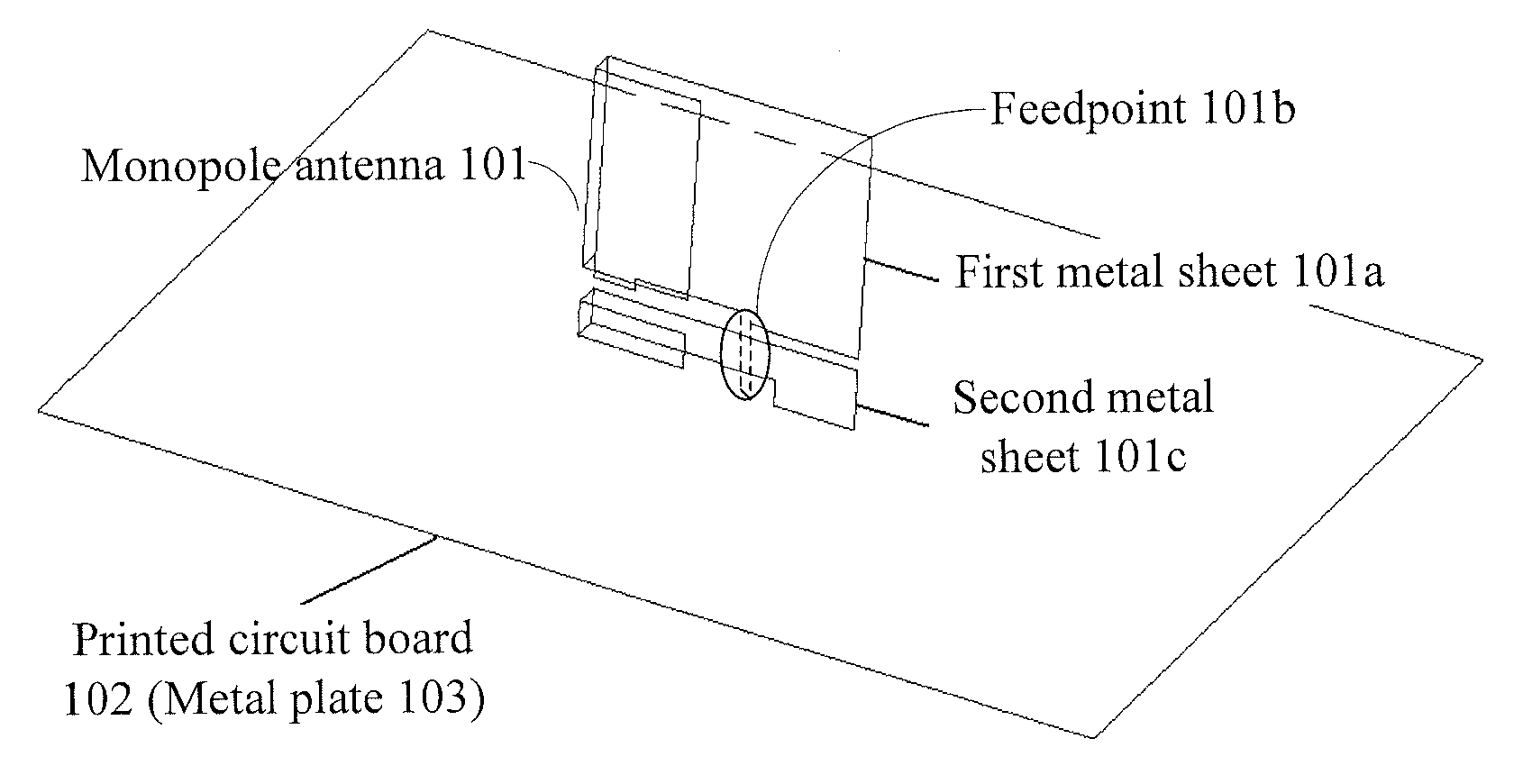
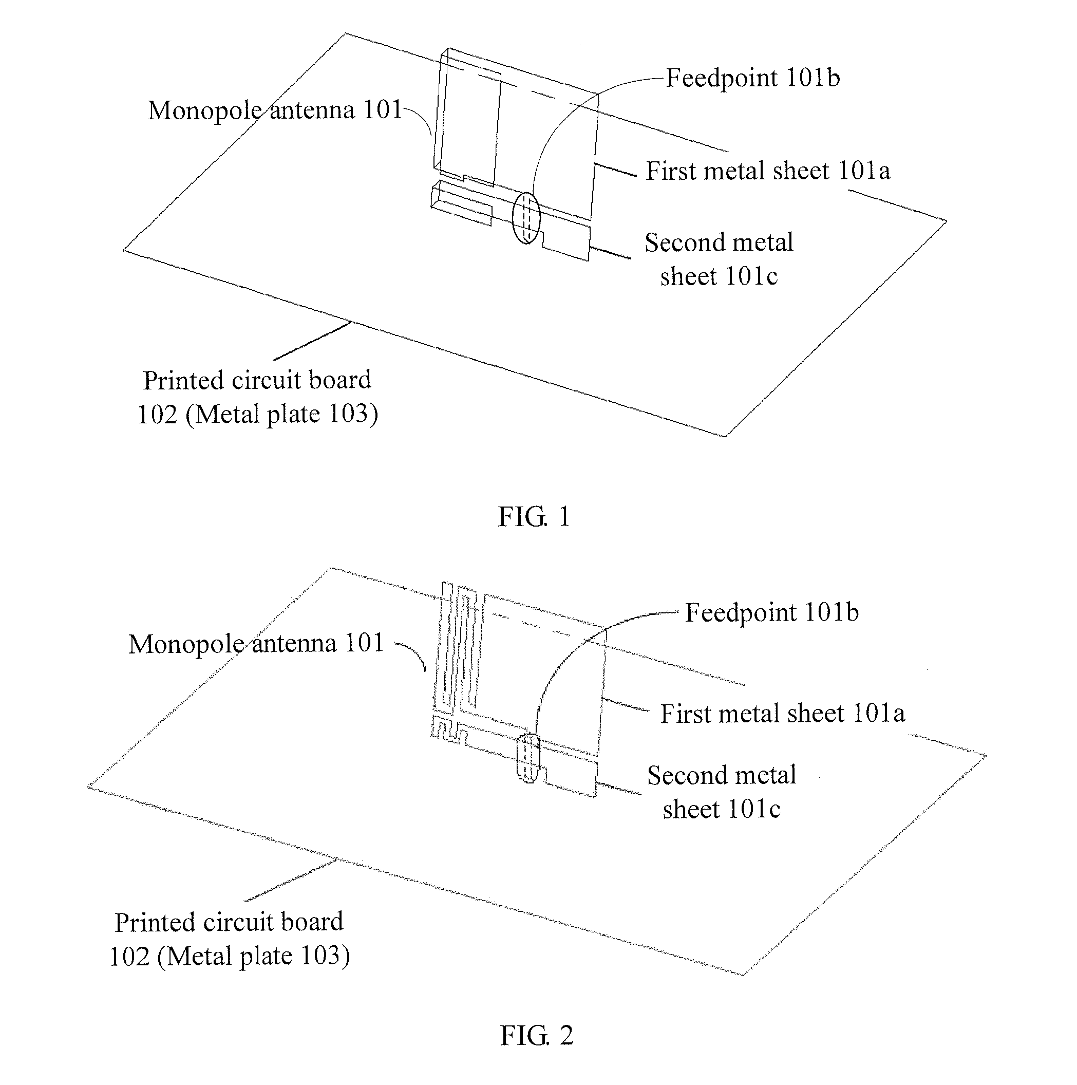
The present invention provides a mobile communication antenna device and a mobile communication terminal device that can increase the bandwidth, enhance the gain, and improve the un-roundness of the pattern of the horizontal plane of the antenna. This is achieved by placing a monopole antenna on one side of the printed circuit board with a distance between it and the printed circuit board less than a certain threshold. The monopole antenna is designed to form a dipole antenna with a mirror image monopole antenna on the other side of the printed circuit board, which is less affected by the printed circuit board and has a higher gain and improved un-roundness of the pattern of the horizontal plane. This allows the antenna to cover GPS and Bluetooth frequency bands without the need for adding new antennas, reducing cost.

Problems solved by technology

However, due to an environment limitation, an existing form of built-in antenna is much poorer than an external antenna in terms of bandwidth, gain, and un-roundness of a pattern of a horizontal plane, which results in a decline in user satisfaction.
Therefore, how to improve related performance specifications of a built-in antenna device becomes extremely urgent.
However, in a case that wireless signals in a rural area are mainly vertically polarized, a bandwidth, a gain, and un-roundness of a pattern of a horizontal plane of the antenna are undesirable, which results in poor user experience.
The bandwidth of the antenna can only meet specification requirements, the gain of the antenna is hard to be increased, and the un-roundness of the pattern of the horizontal plane is difficult to be improved.
As a result, the user experience is still poor.

Method used


Image

  • Mobile communication antenna device and mobile communication terminal device
  • Mobile communication antenna device and mobile communication terminal device
  • Mobile communication antenna device and mobile communication terminal device

Examples


Embodiment Construction

[0017]In order to make the objectives, technical solutions, and advantages of the embodiments of the present invention more comprehensible, the embodiments of the present invention are further described in detail in the following with reference to the accompanying drawings. Here, the exemplary embodiments of the present invention and descriptions are used to explain the present invention, but not intended to limit the present invention.

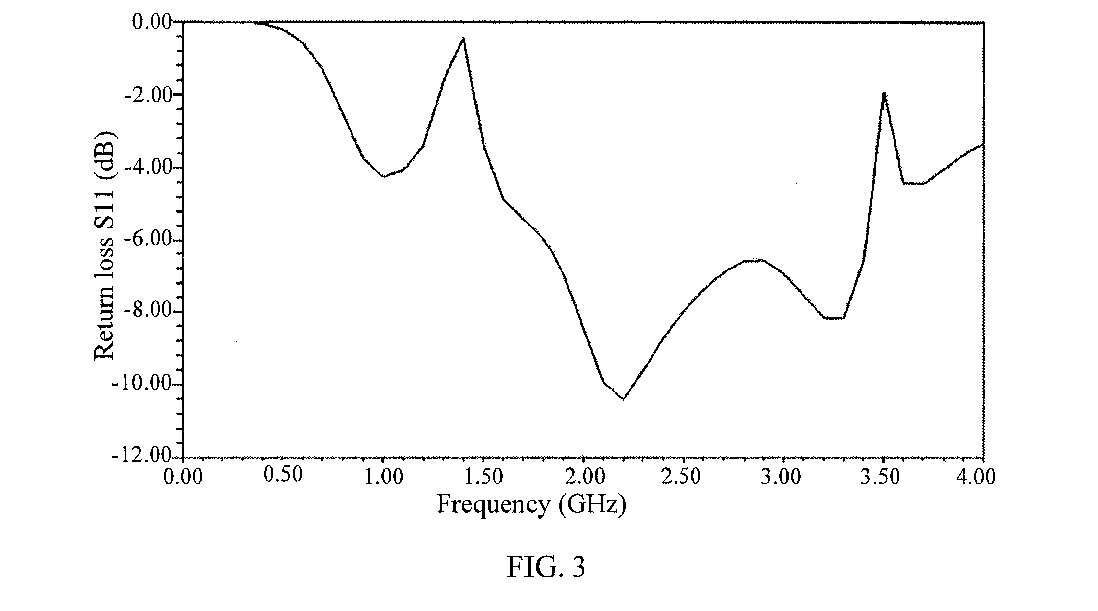
[0018]An embodiment of the present invention provides a new form of built-in antenna, so that a working frequency band of the antenna cover frequency bands which are adopted by GSM850, GSM900, DCS, PCS, UMTS2100, GPS, Bluetooth, and so on and are currently commonly used by mobile communication terminal devices. Meanwhile, a gain of the antenna can reach that of a conventional external antenna. Especially, compared with an existing form of built-in antenna, un-roundness of a pattern of a horizontal plane of the antenna is greatly improved.

[0019]As show...


PUM


Abstract

The present invention discloses a mobile communication antenna device. The device includes: a monopole antenna, placed on one side of a printed circuit board, where a distance between the monopole antenna and a central position of the printed circuit board is less than a threshold, and the monopole antenna includes a first metal sheet which is vertical to the printed circuit board, and is conducted with a circuit of the printed circuit board through a feedpoint. The present invention also discloses a mobile communication terminal device. By adopting the present invention, an ultra wideband antenna may be achieved, thereby making it possible that a mobile communication terminal device product, such as a fixed station, supports more frequency bands.

Description

CROSS-REFERENCE TO RELATED APPLICATIONS[0001]This application is a continuation of International Application No. PCT / CN2011 / 072197, filed on Mar. 28, 2011, which claims priority to Chinese Patent Application No. 201020144966.X, filed on Mar. 26, 2010, both of which are hereby incorporated by reference in their entireties.FIELD OF THE INVENTION[0002]The present invention relates to the field of communications technologies, and in particular, to a mobile communication antenna device and a mobile communication terminal device.BACKGROUND OF THE INVENTION[0003]With the development of wireless communications technologies, wireless performance of a terminal device becomes very important. Meanwhile, a miniaturization tendency of the terminal device further makes that an antenna, which is used to transmit and receive wireless signals, increasingly urgently needs to be converted from a traditional external form to a built-in form. However, due to an environment limitation, an existing form of...

Claims


Application Information

Patent Timeline
Patent Type & Authority Patents(United States)
IPC IPC(8): H01Q1/38H01Q5/357H01Q5/378H01Q1/36H01Q9/42H01Q9/40H01Q1/24H01Q1/48
CPCH01Q1/38H01Q1/243H01Q1/36H01Q9/42H01Q5/357H01Q5/378H01Q9/40H01Q1/48
Inventor ZHU, DEJIN
Owner HUAWEI DEVICE CO LTD
Learn More