
Sample chamber for laser ablation analysis of fluid inclusions and analyzing device thereof

a technology of fluid inclusions and sample chambers, which is applied in the field of oil exploration, can solve the problems of difficult sample chambers, inability to heat up sample chambers, and inability to analyze the composition of fluid inclusions, and achieve the effects of reducing the mass of the sample chamber, reducing the difficulty of analyzing the composition of fluid inclusions, and increasing the volume of the sample chamber

Active Publication Date: 2015-12-08
CHINA PETROCHEMICAL CORP +1
View PDF9 Cites 5 Cited by
  • Summary
  • Abstract
  • Description
  • Claims
  • Application Information

AI Technical Summary

Benefits of technology

The present invention provides a sample chamber with a split-type structure, consisting of a sample cell and a base that are separate from each other. This design allows for easy replacement of the sample chamber by simply changing the sample cell. The base can be made from lighter material to reduce the overall mass of the sample chamber and improve heat transfer efficiency. A viewing hole is also included in the base for improved observation. These features make the sample chamber convenient to operate and improve the efficiency of heating and observation.

Problems solved by technology

As a result, the techniques for analyzing the composition of fluid inclusion are very challenging, and the sample chamber is crucial in the process of analyzing fluid inclusion by laser ablation.
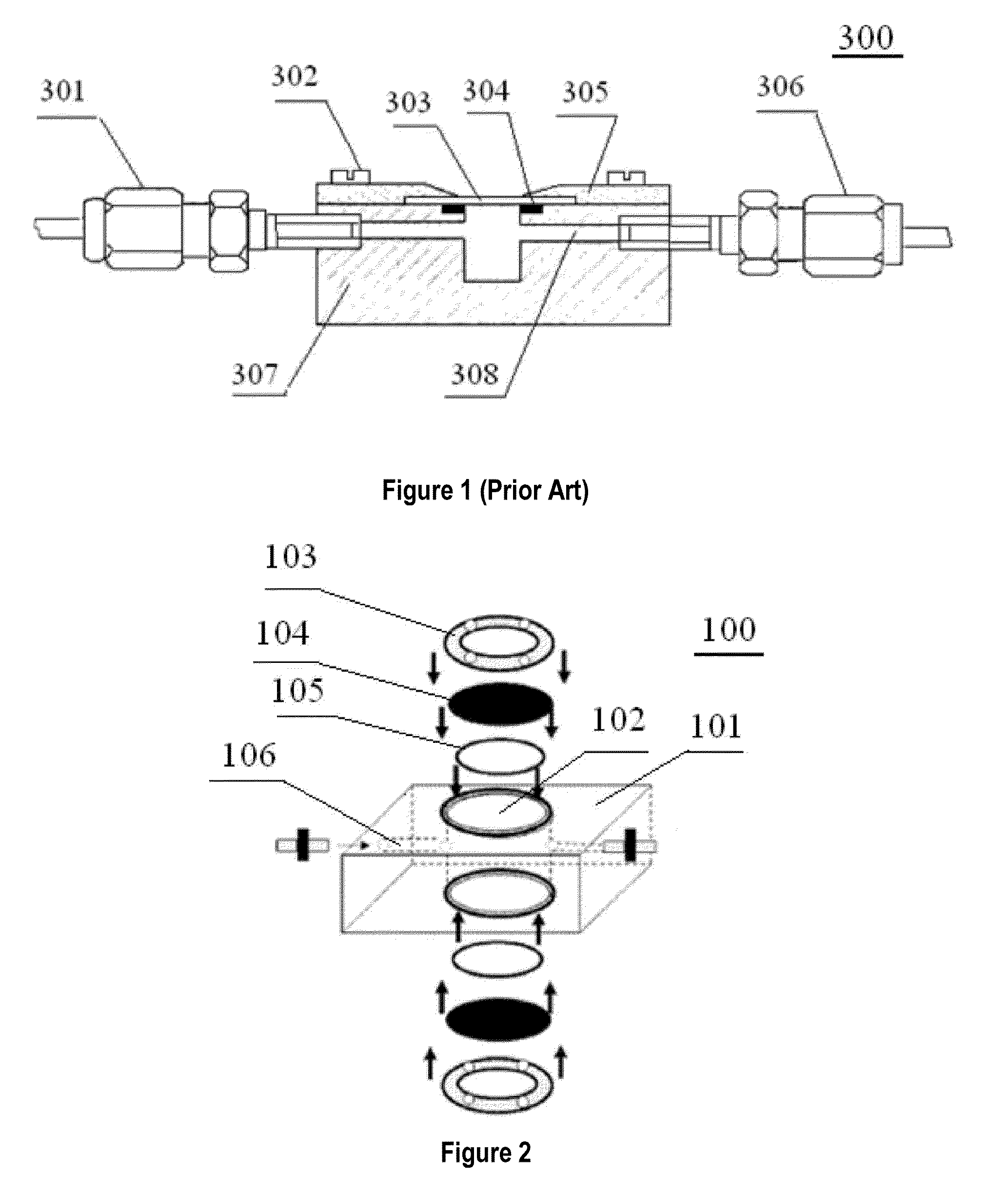
However, the sample chamber 300 still has some defects.
In addition, the sample chamber cannot be heated up in a short time, which enables the whole analyzing process relatively long.
Also, the whole sample chamber has to be replaced in case of a breakdown, which needs to shut down the whole device during replacement, thus causing an inconvenient operation.

Method used


Image

  • Sample chamber for laser ablation analysis of fluid inclusions and analyzing device thereof
  • Sample chamber for laser ablation analysis of fluid inclusions and analyzing device thereof
  • Sample chamber for laser ablation analysis of fluid inclusions and analyzing device thereof

Examples


Embodiment Construction

[0025]In the following a specific embodiment of the present invention will be discussed with reference to FIGS. 2 and 3.

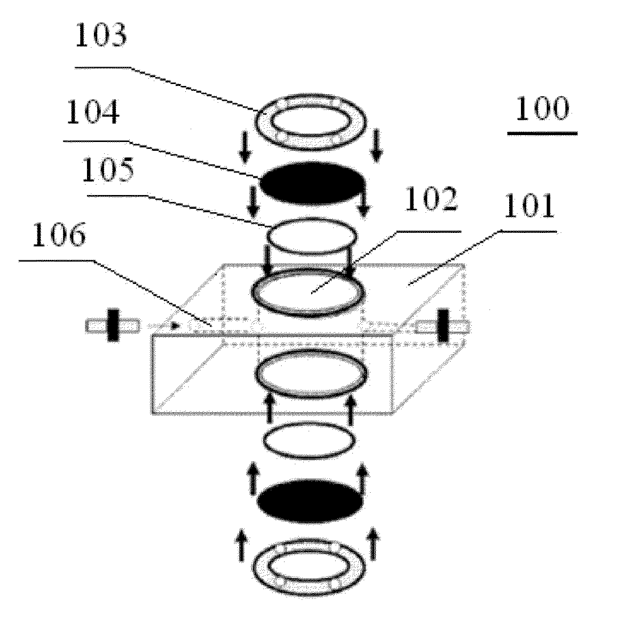
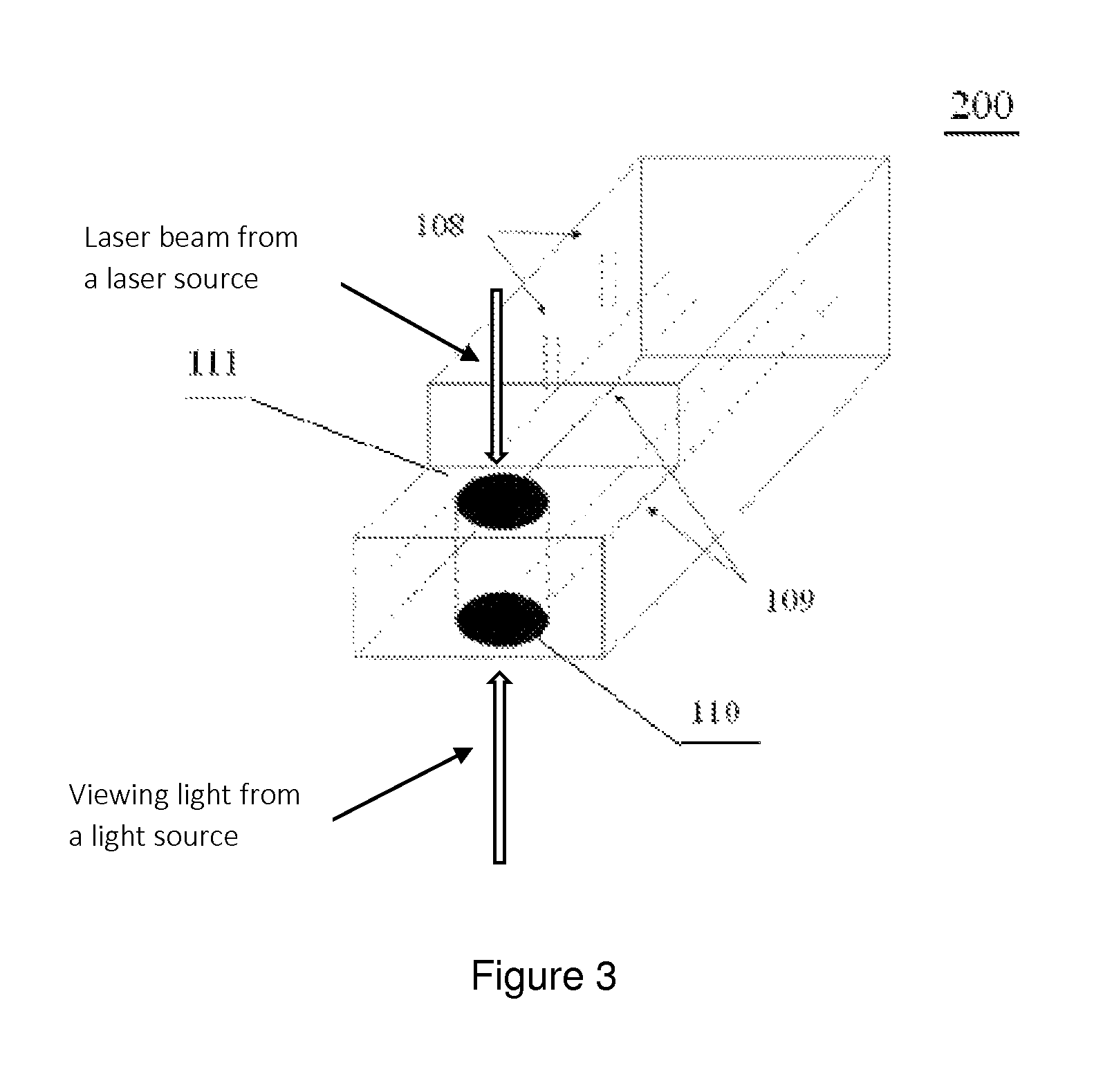
[0026]The sample chamber according to the present invention comprises a sample cell 100 and a base 200 that are separated from each other. As shown in FIG. 2, the sample cell 100 is preferably shaped as a cuboid, and comprises a sample cell through-hole 102 extending along the vertical direction. The sample cell through-hole 102 is preferably located at the center of the sample cell 100. A sample channel 106, which communicates with the sample cell through-hole 102, extends through two opposite sides of the sample cell 100 in a direction transverse to the direction along which the sample cell through-hole 102 extends. Preferably, the sample channel 106 extends along the horizontal direction. In a particular example, threaded ferrules of ⅛ inch made of stainless steel are arranged at both sides of the sample channel 106, in order to connect the sample channel 106 wi...


PUM

PropertyMeasurementUnit
diameteraaaaaaaaaa
transparentaaaaaaaaaa
densityaaaaaaaaaa

Abstract

The present invention relates to a sample chamber for laser ablation analysis of fluid inclusions, comprising a sample cell having a sample cell through-hole extending along the vertical direction and a sample channel extending through the sample cell in a direction transverse to the vertical direction and communicating with the sample cell through-hole. A transparent element is arranged on each of the top and bottom sides of the sample cell through-hole, and is fixed to the sample cell through a fixing ring. The sample chamber further comprises a base comprising a viewing hole and a receiving portion for receiving the sample cell, wherein the viewing hole is coaxially aligned with the sample cell through-hole when the sample cell is placed within the receiving portion. According to the sample chamber of the present invention, it is only necessary to change the sample cell during replacement of the sample chamber, which leads to a convenient operation. At the same time, light from the microscope can pass through the viewing hole, so that the effect of observation is improved.

Description

CROSS REFERENCE TO RELATED APPLICATION[0001]This application claims priority to Chinese Patent Application No. CN 201110319046.6 filed on Oct. 19, 2011, which hereby is incorporated herein in its entirety.TECHNICAL FIELD[0002]The present invention relates to the field of oil exploration, in particular relates to a sample chamber for laser ablation analysis of fluid inclusions and a device for laser ablation analysis of fluid inclusions which comprises the above-mentioned sample chamber.BACKGROUND[0003]It is well know that fluid inclusion is a kind of sample reserved in geological body during the formation of rocks, minerals, deposits and so on. The fluid inclusion can provide various kinds of information, such as the formation conditions of rocks and minerals, and the storage, migration and evolution of oil and natural gas and the like.[0004]Oil-bearing fluid inclusions generally exist in the samples of sedimentary rocks. Once the oil / gas components in the fluid inclusion are entrap...

Claims


Application Information

Patent Timeline
Patent Type & Authority Patents(United States)
IPC IPC(8): G01N15/14G01N21/03G01N33/24G01N21/71G01N1/04
CPCG01N21/0332G01N21/03G01N21/718G01N33/241G01N2001/045G01N2021/0389
Inventor ZHANG, ZHIRONGTENGERRAO, DANSHI, WEIJUNJIANG, QIGUIQIN, JIANZHONGZHANG, QUXI, BINBIN
Owner CHINA PETROCHEMICAL CORP
Learn More