System and method for sanitizing pneumatic conveying piping

a pneumatic conveying and sanitizing technology, applied in the direction of cleaning, cleaning process and apparatus, chemistry apparatus and process, etc., can solve the problems of high particle-to-particle and particle-to-pipe interaction, cip system requires a very high volume of cleaning fluid, and sanitize the interior of the pipe. , to achieve the effect of low volume of sanitizing solution, easy retrofitting into existing systems, and convenient us

Active Publication Date: 2015-12-15
HORIZON SYST
View PDF29 Cites 3 Cited by
  • Summary
  • Abstract
  • Description
  • Claims
  • Application Information

AI Technical Summary

Benefits of technology

[0013]Objects of the present inventive concept include, but are not necessarily limited to, providing a system and method for sanitizing pneumatic conveying lines that is easy to use, utilizes a relatively low volume of sanitizing solution, can be easily retrofitted into existing systems, and / or allows for repeatability of sanitization results.

Problems solved by technology

This also results in high particle-to-particle and particle-to-pipe interaction.
For example, when the material being conveyed is a food product (whether for human or pet consumption) that is highly susceptible to contamination by bacteria or other contaminants, it is often necessary to sanitize the interior of the pipes.
In some cases contaminated product will unknowingly be conveyed through a system (such a pet food contaminated with salmonella), and when such contamination is discovered, the entire system must be brought offline and sanitized before it can be used for conveying any other materials.
Full wet CIP systems require usage of a very high volume of cleaning fluid, as well as complicated, specially designed pumps, fluid tanks, return piping (e.g. to create the loop), etc. to sanitize conveying lines.
Proper disposal of the used sanitizing fluid is often an issue, particularly as environmental regulations increase.
In addition, due to the large amount of wet residue remaining of the sanitizing fluid, the conveying lines must remain offline for extended periods of time until they are allowed to dry out.
As such, full wet CIP systems are often not practical for use in sanitizing conveying lines in which primarily dry product is transported.
Such methods result in uneven application of sanitizing solution, as more solution will be applied early on when the pig is more heavily soaked, and decrease as the pig travels through the pipes.
In addition, due to the materials used to make sanitizing pigs capable of soaking up fluid, such pigs are not compatible with a number of sanitizing solutions, which would destroy the pig material.
Thus, such systems leave a large amount of wet residue behind, creating the same or similar disposal and drying time difficulties discussed above with respect to full wet system.
The alcohol based sanitizing solution of the BioMist system is often undesirable due to the potential for vapor build up in enclosed system to potentially explosive levels.
Moreover, these type of systems are very time consuming, require operators to access both the launch side and receiving side of the system, and expose operators to the interior of the system to retrieve the pig and tether lines.
Refraction of the spray rigs is often difficult because the pig tends to get stuck in the pipeline.
Thus, such systems often require removal of the pig from the spray rig prior to retraction of the rig from the pipeline.
Moreover, in many dilute phase conveying systems, the high velocity of travel of the pig through the pipes can result in damage to the spray nozzle.

Method used


Image

  • System and method for sanitizing pneumatic conveying piping
  • System and method for sanitizing pneumatic conveying piping
  • System and method for sanitizing pneumatic conveying piping

Examples


Embodiment Construction

[0029]As required, a detailed embodiment of the present invention is disclosed herein; however, it is to be understood that the disclosed embodiment is merely exemplary of the principles of the invention, which may be embodied in various forms. Therefore, specific structural and functional details disclosed herein are not to be interpreted as limiting, but merely as a basis for the claims and as a representative basis for teaching one skilled in the art to variously employ the present invention in virtually any appropriately detailed structure.

[0030]The inventive concept relates to a system and method for sanitizing pneumatic conveying lines. It will be appreciated that although the embodiments of the system of the inventive concept described herein are particularly useful for sanitizing conveying lines in dilute phase conveying systems, some embodiments will likewise be utilized for sanitizing conveying lines of dense phase conveying systems, or of any other type of conveying syste...


PUM


Abstract

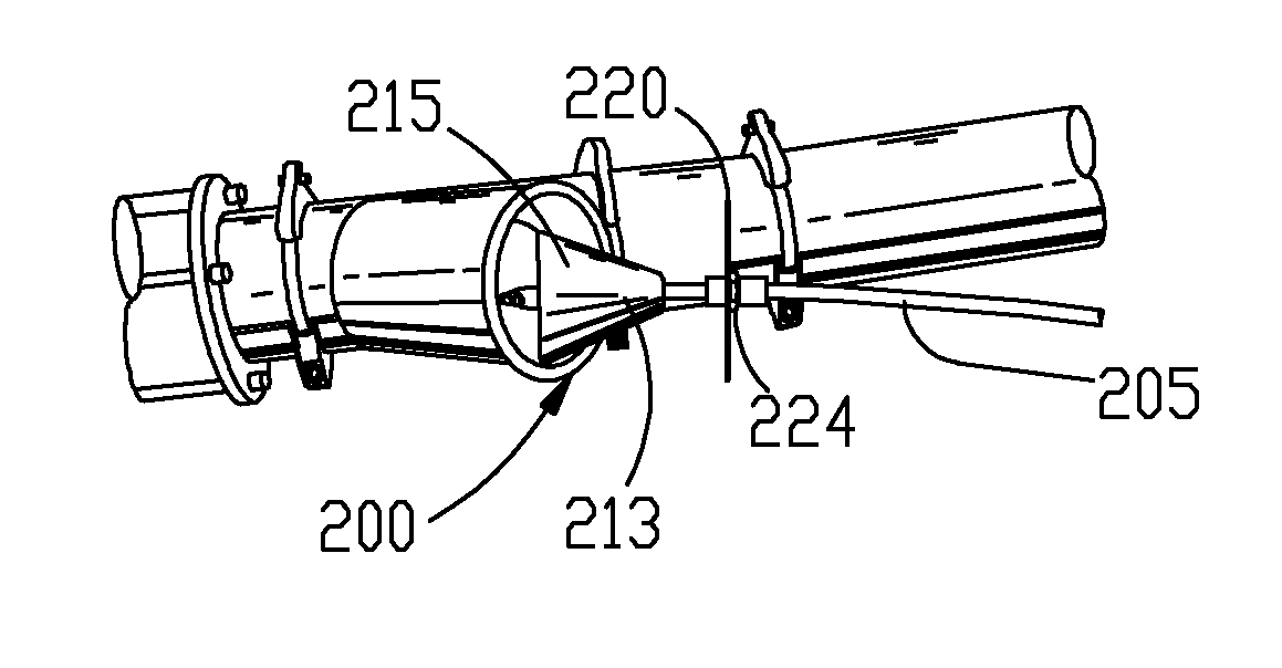
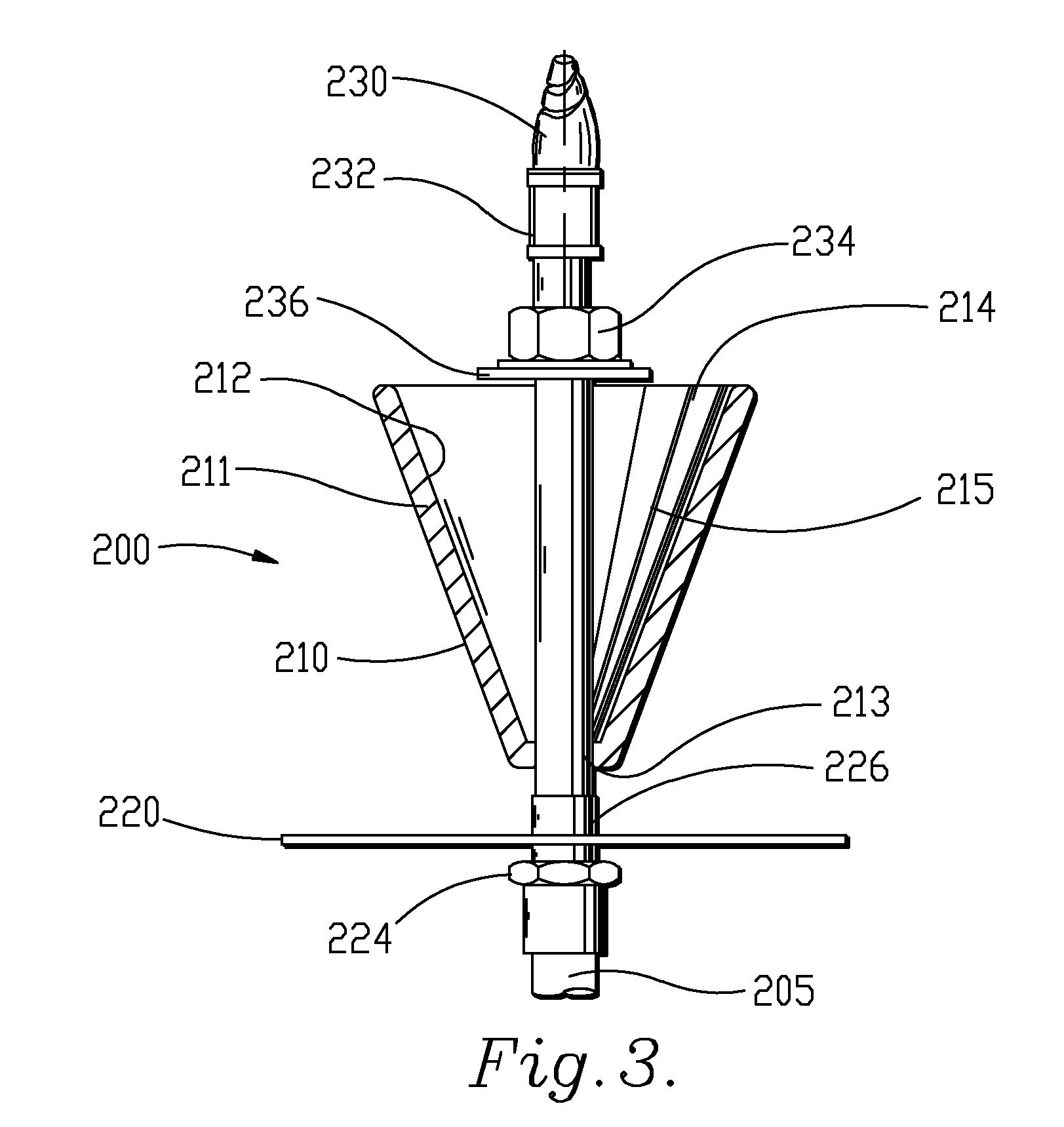
A system and method for sanitizing pneumatic conveying piping is provided. The system includes a motorized hose reel with a pig attached to the end of the hose. The pig is smaller in diameter than the inner diameter of the pipe through which it is conveyed. The decreased size of the pig keeps the conveying speed of the pig through the pipes down, while at the same time providing sufficient force to pull the supply hose attached to the pig through the pipes with the pig. The pig of some embodiments of the inventive concept is shaped as a hollow cone or frustoconical shape. Such a shape reduces weight of the pig and also allows the hose to be inserted through the body of the pig with a spray nozzle at the end. The hollow cone shape deflects relatively easily to allow the pig to go around corners or other obstructions. Also, such a pig design automatically centers the nozzle within the pipe during spraying. The pig of some embodiments is further made of a urethane material that is easily washable and non-porous to maximize sanitary conditions.

Description

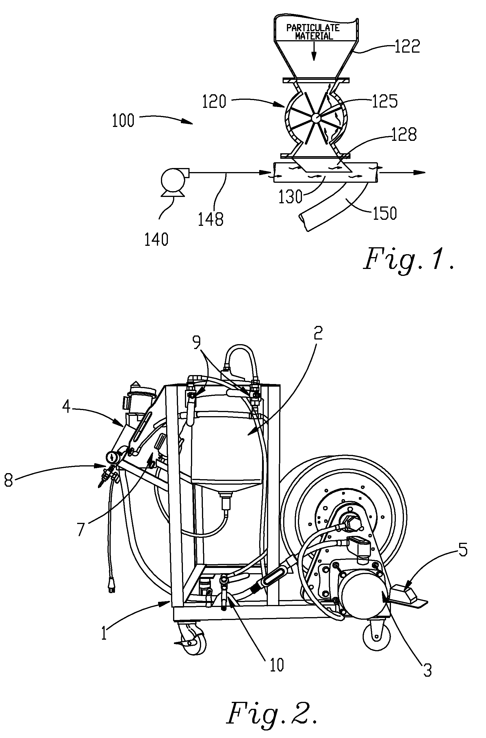
FIELD[0001]The present inventive concept relates generally to the field of pneumatic conveying systems used to transport particulate material. Particularly, the inventive concept relates to a system and method for sanitizing pneumatic conveying piping.BACKGROUND[0002]Pneumatic conveying systems are used to transport large quantities of particulate material through pipes. Examples of particulate material include powders, granules, pellets, seeds, beans, nuts, pasta, pet foods, snack foods, and other similar items. In a common pneumatic conveying system, a fluid, usually air, is blown through the pipes. The air enters the pipes through a filtered air inlet. The particulate material enters the pipes through a material inlet. The air is mixed with the particulate material and together, the air and particulate material moves through the pipes. Both the air and the particulate material exit the pipes through an outlet.[0003]Dilute phase conveying occurs when the particulate material is tr...

Claims


Application Information

Patent Timeline
Patent Type & Authority Patents(United States)
IPC IPC(8): B08B9/043B08B9/053F16L55/46B65G53/52B08B9/055B65G45/00B08B9/00
CPCB08B9/0433B08B9/053B08B9/0535B65G53/521F16L55/46B65G45/00
Inventor BAKER, TODD
Owner HORIZON SYST
Why Eureka
Try Eureka