Fluid control device

a control device and flue gas technology, applied in mechanical devices, valve housings, transportation and packaging, etc., can solve the problems of contaminated inside the chamber with resulting impurities, and achieve the effect of easy purging, easy assembly and disassembly, and easy control of flows

Active Publication Date: 2015-12-15
FUJIKIN INC
View PDF15 Cites 7 Cited by
  • Summary
  • Abstract
  • Description
  • Claims
  • Application Information

AI Technical Summary

Benefits of technology

[0005]An object of the present invention is to provide a fluid control device that can avoid the problem that inside of a chamber is contaminated with impurities resulting from a reaction product.
[0007]According to the fluid control device wherein the two opening and closing valves having an identical shape are disposed symmetrical to each other, the fluid passages from fluid inlets to fluid outlets of the respective opening and closing valves have an equal volume and an equal length, and the two fluid pas sages for the fluids to thereafter travel through also have an equal length. Therefore, the flow control of the two different fluids is facilitated. Further, the fluid control device lets the two different fluids flow through the different fluid discharge passages, thereby avoiding any product produced by the retained and mixed fluids. This eliminates the risk of contamination with impurities resulting from the reaction product, successfully introducing the required fluids into the chamber.
[0009]This arrangement facilitates assembling and disassembling of the respective structural elements, providing a good maintainability.
[0012]When the purge fluid is introduced through the purge valves after the two different fluids (for example, process gasses) are introduced and discharged, the process gases can be easily purged. The fluid control device having these remarkable advantages can be easily assembled and disassembled.
[0013]According to the fluid control device of the present invention, the two opening and closing valves having an identical shape are disposed symmetrical to each other, the fluid discharge passages having an equal length are disposed in parallel with each other in outlets of the opening and closing valves, and the connection member attachable to the chamber and having the fluid passages formed in an equal length to and communicating with the fluid discharge passages are provided in the outlets of the two fluid discharge passages. The fluid control device thus structured can easily control the flows of two different fluids, avoid any product produced by the retained and mixed fluids and eliminate the risk of contamination with impurities resulting from the reaction product, successfully introducing the required fluids into the chamber.

Problems solved by technology

Depending on types of the introduced fluids, a reaction may be generated between the fluids mixed with each other, and a reaction product thereby generated near a discharge port extending from the fluid control device invites the problem that inside of the chamber is contaminated with resulting impurities.

Method used


Image

  • Fluid control device
  • Fluid control device
  • Fluid control device

Examples


Embodiment Construction

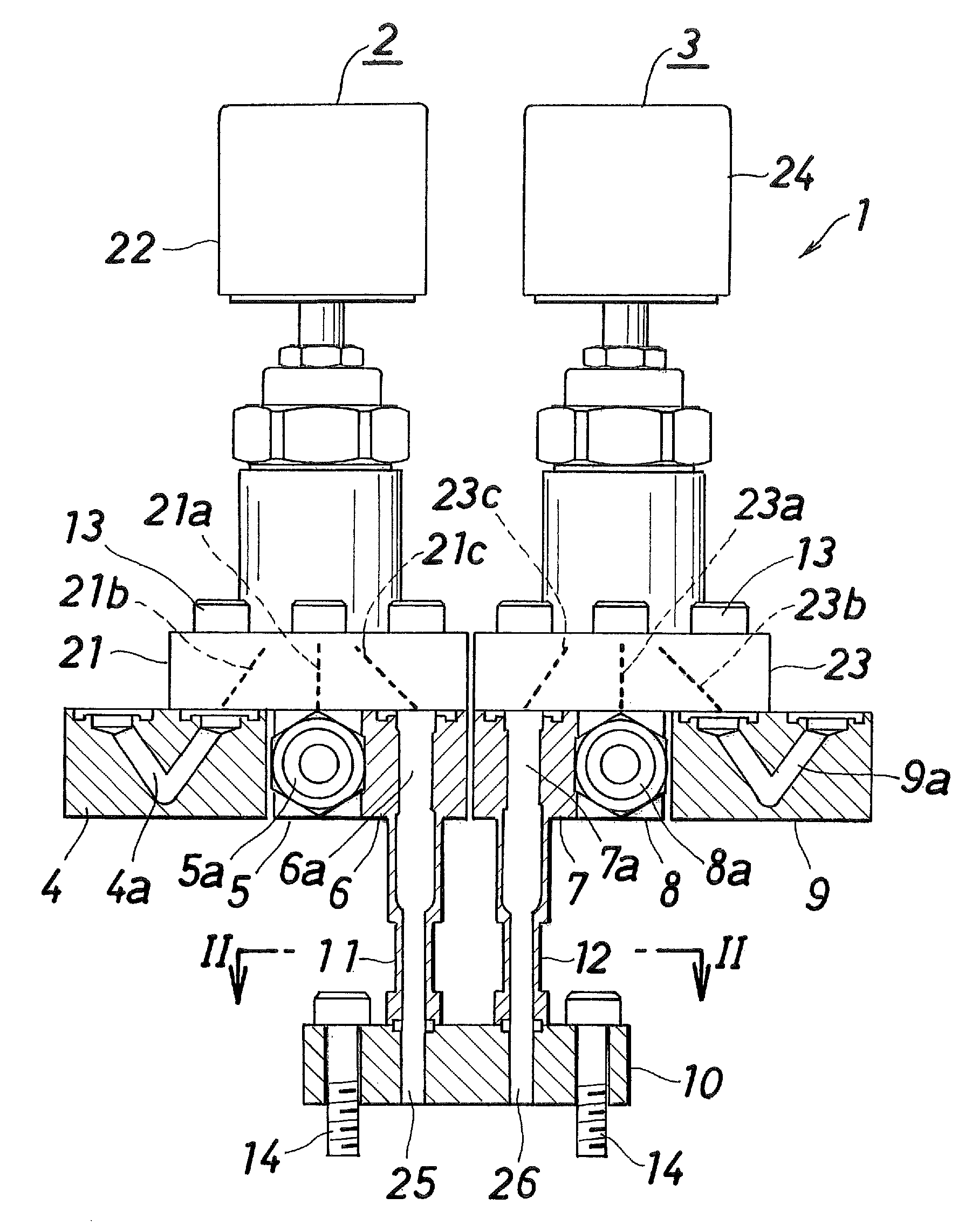
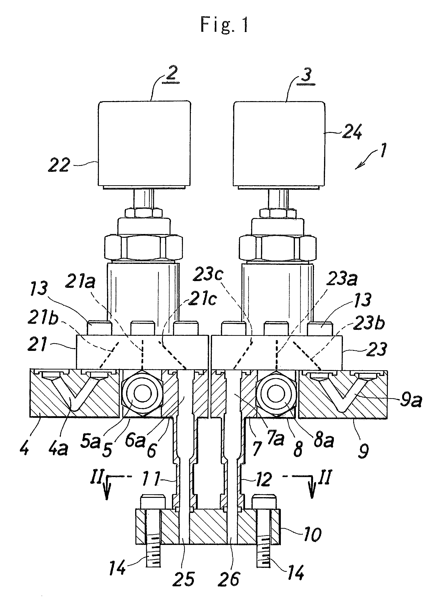
[0018]Hereinafter, preferred embodiments of the present invention are described with reference to the drawings. All of expressions indicating directions in the description hereinafter given, upper, lower, right, and left, are upper, lower, right, and left directions illustrated in FIG. 1.

[0019]A first preferred embodiment of a fluid control device 1 according to the present invention is configured to introduce and discharge two different types of fluids selectively to and from a chamber (not illustrated in the figures). As illustrated in FIG. 1, the fluid control device includes: left and right opening and closing valves 2 and 3 having an identical shape and provided in an upper stage of the device; six cuboidal passage blocks 4, 5, 6, 7, 8, and 9 provided side by side in a lower stage of the device to support the opening and closing valve 2 and 3; a connection member 10 provided below the six passage blocks 4, 5, 6, 7, 8, and 9 and attached to the chamber; and fluid discharge tubes...


PUM


Abstract

A fluid control device includes two opening and closing valves 2, 3 disposed symmetrical to each other and having an identical shape, two fluid discharge passages 6, 7, 11, 12 having an equal length and provided in parallel with each other in outlets of the opening and closing valves 2, 3, and a connection member 10 attachable to a chamber and having two fluid passages 25, 26 formed in an equal length to and communicating with the two fluid discharge passages 6, 7, 11, 12, the connection member being provided in outlets of the two fluid discharge passages 6, 7, 11, 12.

Description

BACKGROUND OF THE INVENTION[0001]The present invention relates to a fluid control device used in, for example, a semiconductor manufacturing apparatus, specifically to a fluid control device in which two different types of fluids can be selectively introduced and discharged.[0002]According to the industrial needs, some fluid control devices used in semiconductor manufacturing apparatuses are configured to supply two different types of gases to a treatment chamber. Patent Literature 1 (Japanese Patent Application Laid-Open No. 2004-214622) discloses an example of such a fluid control device in which two different types of fluids can be selectively introduced and discharged. The fluid control device disclosed in Patent Literature 1 has a cylindrical body (head assembly) and two opening and closing valves fitted to the body, wherein the body is attachable to an opening provided in a capping member of a treatment chamber.[0003]The two opening and closing valves of the fluid control devi...

Claims


Application Information

Patent Timeline
Patent Type & Authority Patents(United States)
IPC IPC(8): F16K11/20F16K27/00
CPCF16K27/003Y10T137/87249H01L21/02
Inventor KURIKI, HARUHIKOMATSUDA, TAKAHIROKOYOMOGI, MUTSUNORIMAKINO, MEGUMU
Owner FUJIKIN INC
Why Eureka
Try Eureka